

Multi-position optic mount
a multi-position, optic mount technology, applied in the direction of mountings, optics, instruments, etc., can solve the problems of time-consuming and labor-intensive realignment of mirrors, and the need for accurate positioning of mirrors
- Summary
- Abstract
- Description
- Claims
- Application Information
AI Technical Summary
Problems solved by technology
Method used
Image

Examples
Embodiment Construction
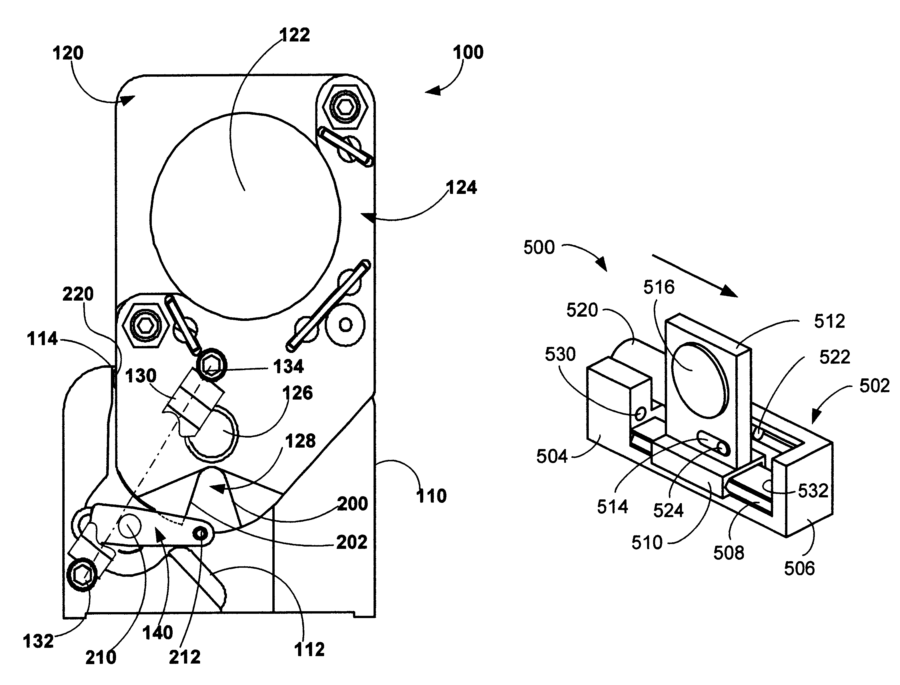
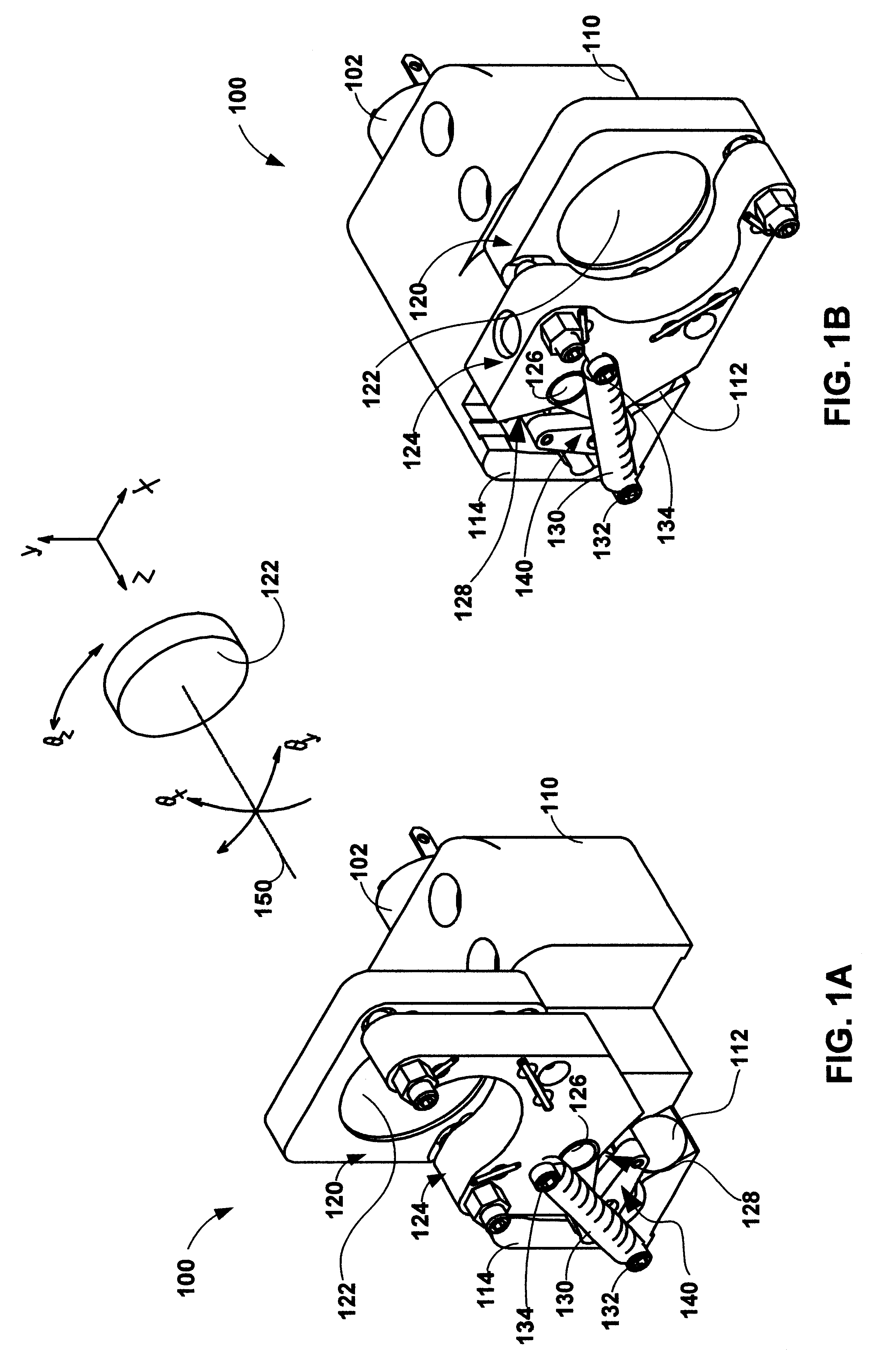
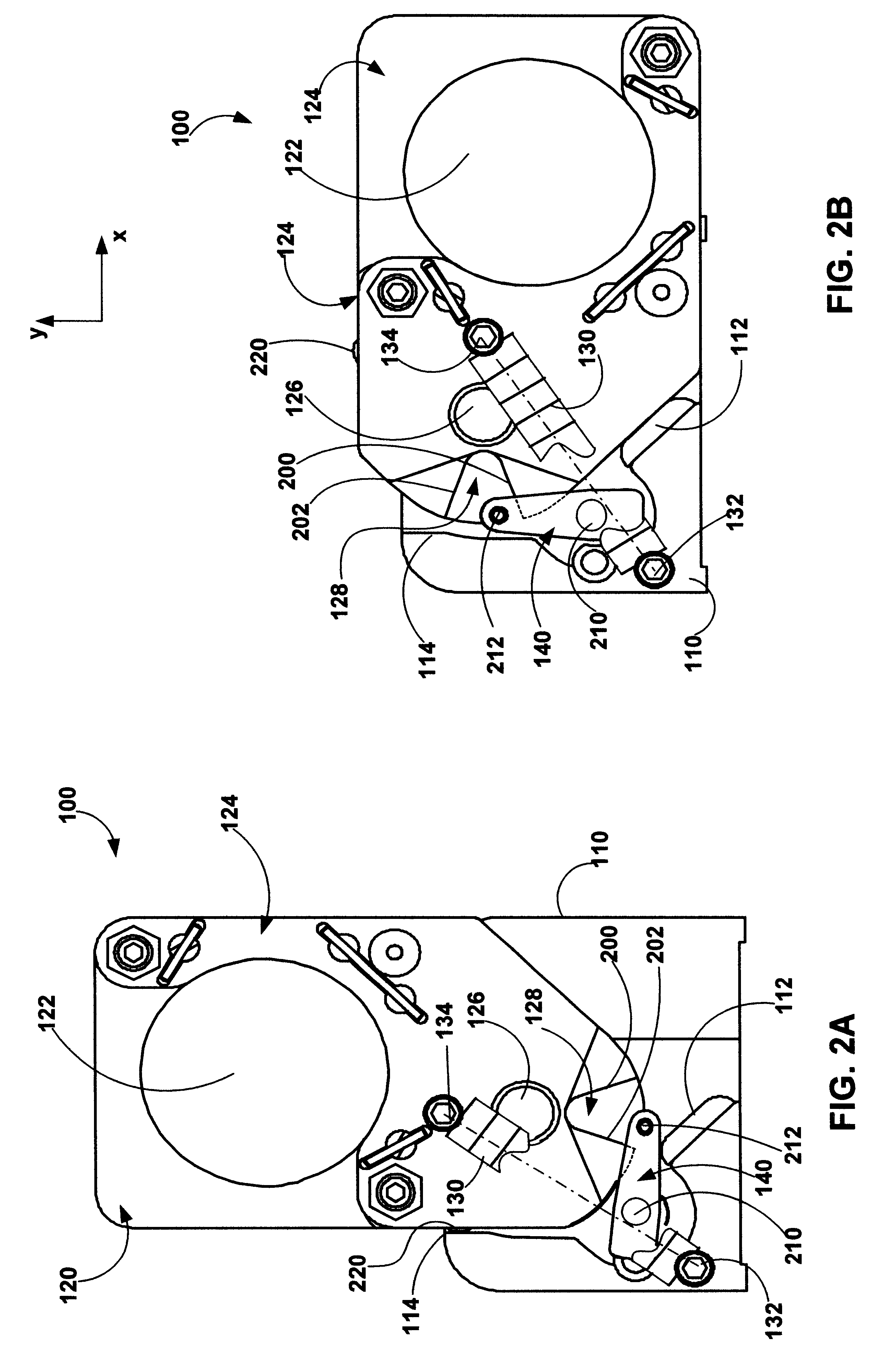
A multi-position optic mount is disclosed which provides for automatic movement of an optic element between an engaged position in which the optic element intersects an optical path, and a disengaged position in which the optic element avoids an optical path. The optic mount may be used for a broad range of optical elements including: lenses, filters, etalons, gratings, retroreflectors, wave guides, fiber optics, lasers, photo-detectors, etc. A unique activation capability is provided in which an active actuator and passive actuator are utilized to move the mount between the engaged and disengaged positions.
FIGS. 1A-B are isometric top side views of the multi-position optic mount 100 in the engaged and disengaged positions respectively. In the engaged position an optic element, e.g., lens, is positioned to intersect the optical path 150. In the disengaged position it avoids the optical path. In this embodiment the engaged and disengaged positions are arcuately separated by approxima...
PUM
 Abstract
Description
Claims
Application Information