Lighting system for rotating object

Inactive Publication Date: 2001-08-07
EMILSSON TRYGGVI
View PDF3 Cites 21 Cited by
  • Summary
  • Abstract
  • Description
  • Claims
  • Application Information

AI Technical Summary

Problems solved by technology

Unfortunately, the regular pulsations of the LED light sources are not in any way controllable by the user.
The chemiluminesc

Method used


Image

  • Lighting system for rotating object
  • Lighting system for rotating object
  • Lighting system for rotating object

Examples


Embodiment Construction

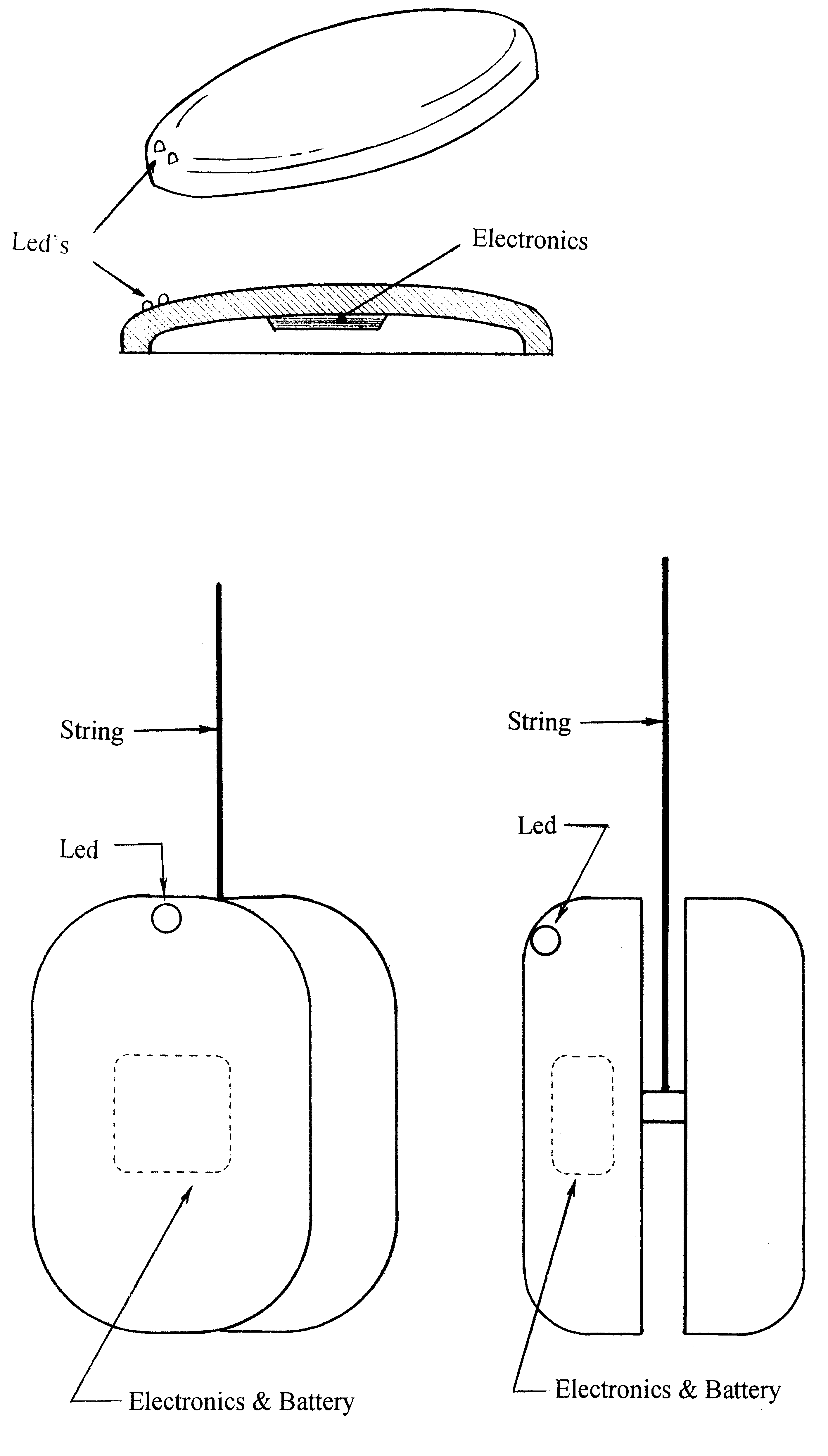
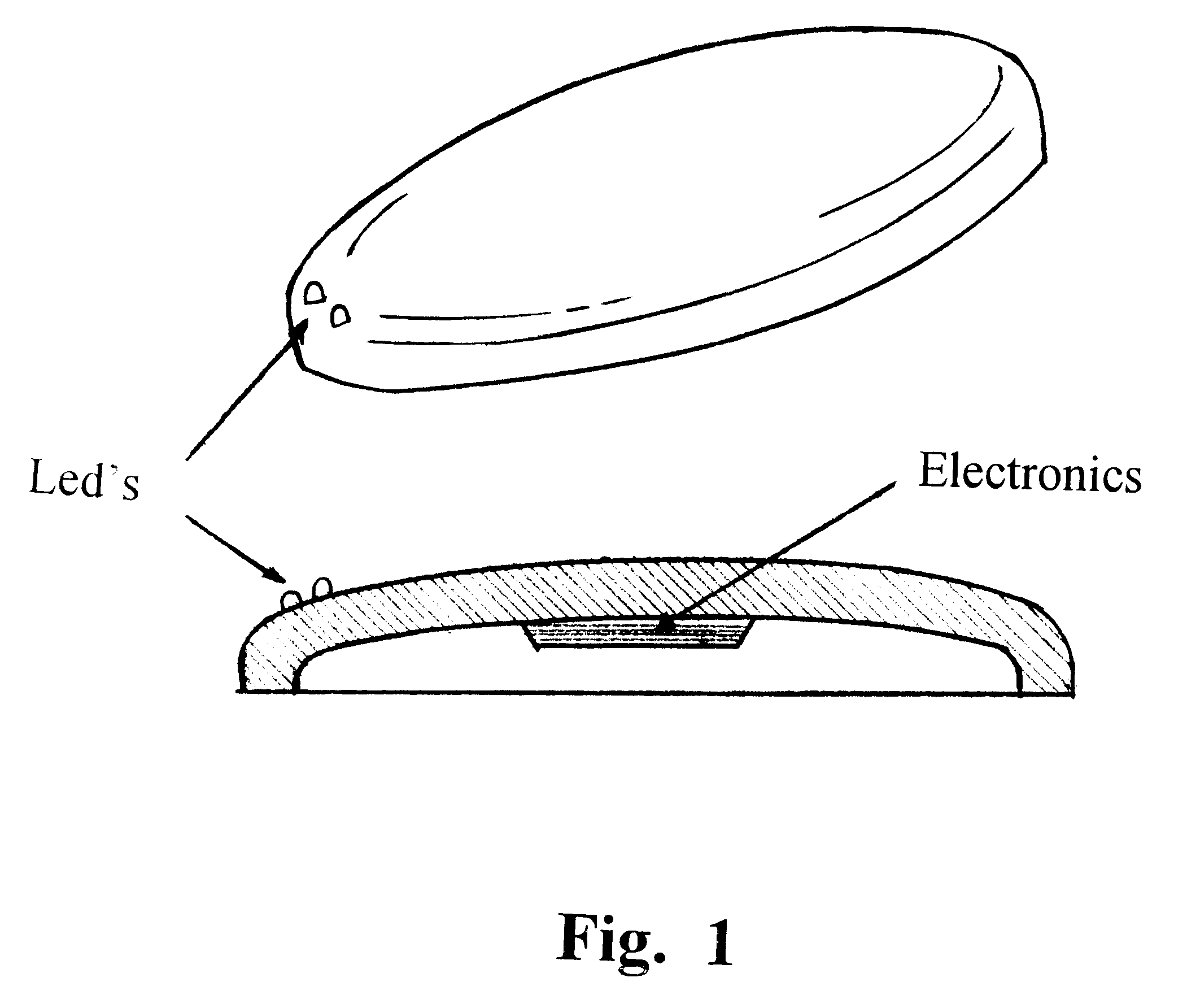
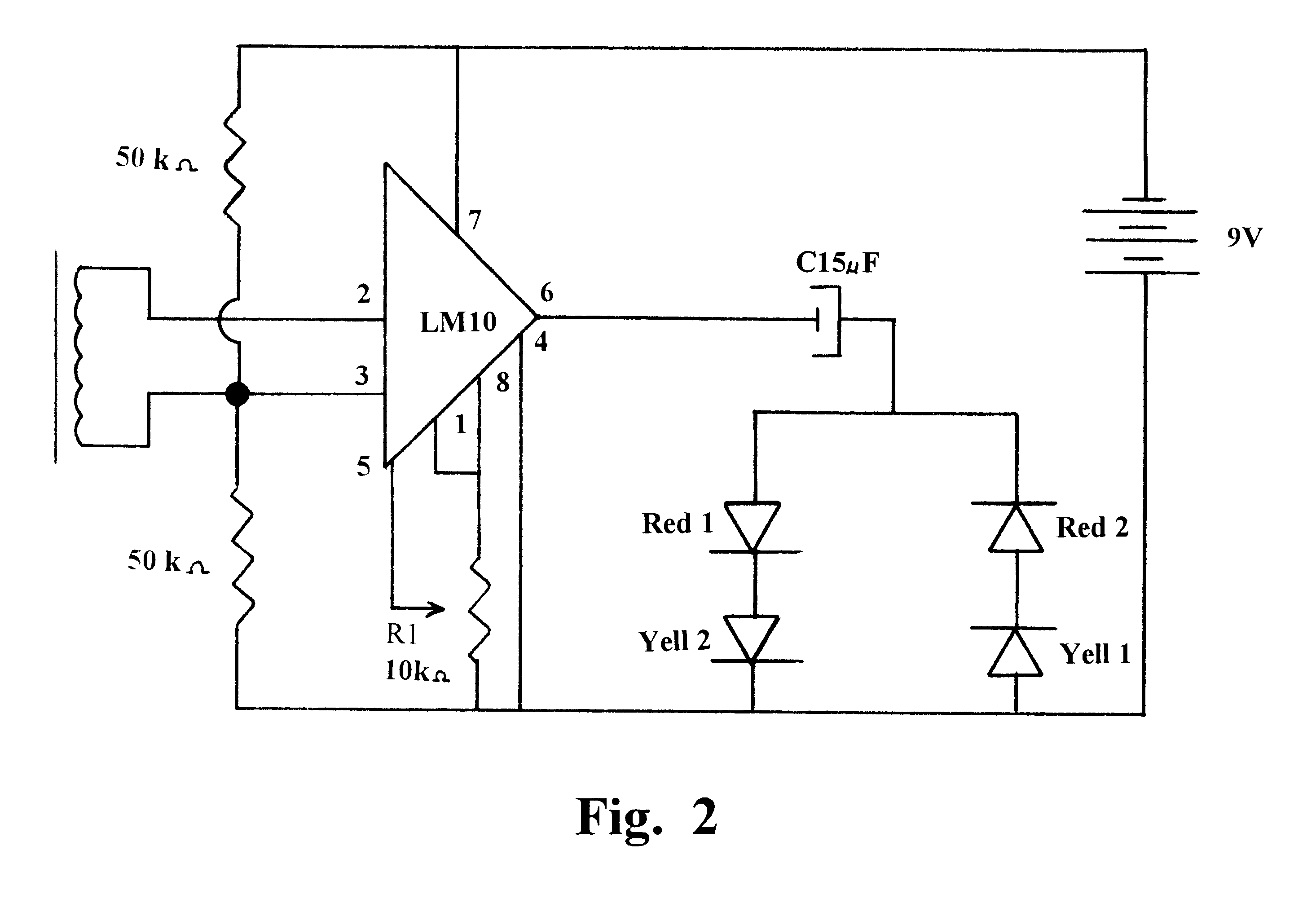
In one embodiment of the present invention is presented a flying object or saucer disk toy, such as a "FRISBEE" brand toy, in which a lighting system is provided wherein the lights blink on and off in exact synchrony with the rotation of the disk. By "disk", "disc" or "object" herein is meant both solid and ring-shaped articles. The timing of the light blinking is controlled by a sensor means which determines the angular orientation of the disk object relative to any, or the Earth's, magnetic field. In this embodiment of the invention, the sensor means can be, for example, a thin bar of magnetically "soft" iron wound with many turns of thin insulated copper wire which forms a coil. One example would be a thin bar of soft iron, 3 inches long and 1 / 8 inch thick, wound with approximately 1500 to 2000 turns of insulated copper wire. When the object spins, the Earth's magnetic field induces a voltage in said coil, according to Faraday's Law of induction. The voltage induced in the coil i...


PUM


Abstract

This invention relates to a lighting system for a rotating object wherein the lights are made to appear stationary by being turned on and off in synchrony with the rotation of the object. This synchronization is achieved by utilizing magnetic field sensors which determine the instantaneous orientation of the object relative to the Earth's magnetic field.

Description

FIELD AND BACKGROUND OF THE INVENTIONThis invention relates generally to lighting systems for rotating objects, and in particular to a flashing light system for a so-called "flying saucer" toy.The well known flying saucer toy is simply a light-weight disc having aerodynamic characteristics enabling it to travel considerable distances when thrown and which spins during flight. A common tradename for such a device is the "FRISBEE" type flying disc. Prior art flying disc toys have been enhanced with lights mounted thereon to add interest and entertainment. Typical of such flying disc lighted toys are those disclosed in U.S. Pat. No. 3,786,246 utilizing chemiluminescence or the battery powered flashing light system described in U.S. Pat. No. 3,812,614.Later systems used light emitting diodes (LEDs) as a light source, powered by small low voltage batteries. A few flying discs have provided circuitry to apply a square wave or similar cyclic voltage to the LEDs. This type of circuitry has ...

Claims


Application Information

Patent Timeline
IPC IPC(8): A63H1/30A63H1/00A63H1/24A63H33/00A63H33/18A63H33/22
CPCA63H1/24A63H33/18A63H1/30
Inventor EMILSSON, TRYGGVI
Owner EMILSSON TRYGGVI
Why Eureka
Try Eureka