Compact cable anchor for retainment and attachment of cables and tubing

a cable and tubing technology, applied in the field of cable anchors, can solve the problems of not compact in design, inability to be used, and inability to anchor separate cable clips prior art in a fixed position

Inactive Publication Date: 2001-08-21
JENNINGS GILBERT M +1
View PDF34 Cites 64 Cited by
  • Summary
  • Abstract
  • Description
  • Claims
  • Application Information

AI Technical Summary

Problems solved by technology

In many cases the prior art can't be used to anchor an attached separate cable clip in a fixed position.
The difficulties with the prior art cable anchors they are not compact in design and lack the ability to be used as a cable clip with its own anchor an as a cable anchor for attachment of a separate cable clip.
Therefore, it costs more to manufacture and cannot be used as an attachment anchor for a separate cable clip.
Another type fastener with a tapered section and a slot is made of two pieces which must be used together to accommodate each other and must be hammered together causing a problem at assembly of the attached cable clip.
The center piece must be hammered fully home making it very difficult in placing one object to another object without damaging the object being attached to the prior art fastener.
Therefore, this design is such that the connector can become loose and can separate from the inclined surfaces causing the connector to detach itself from the inclined surfaces thereby having a failure.
Therefore, this prior art is limited to a cable clamp and not able to be used as a cable anchor for a separate cable clip.
Therefore, this design is limited for retainment of cables and cannot be used to attach other type cable clips to it.
Therefore, this design is not a compact cable anchor for retainment and attachment for cables or tubing.
It cannot be used to retain a cable in a permanent position because of the open space at the top of the saddle.
Therefore, this design is limited to retaining a cable and is not a compact cable anchor for retainment and attachment of a separate

Method used


Image

  • Compact cable anchor for retainment and attachment of cables and tubing
  • Compact cable anchor for retainment and attachment of cables and tubing
  • Compact cable anchor for retainment and attachment of cables and tubing

Examples


Embodiment Construction

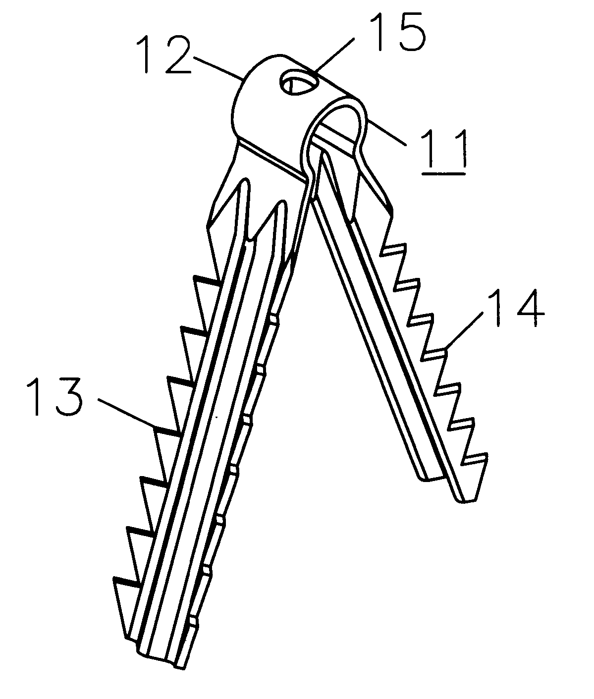
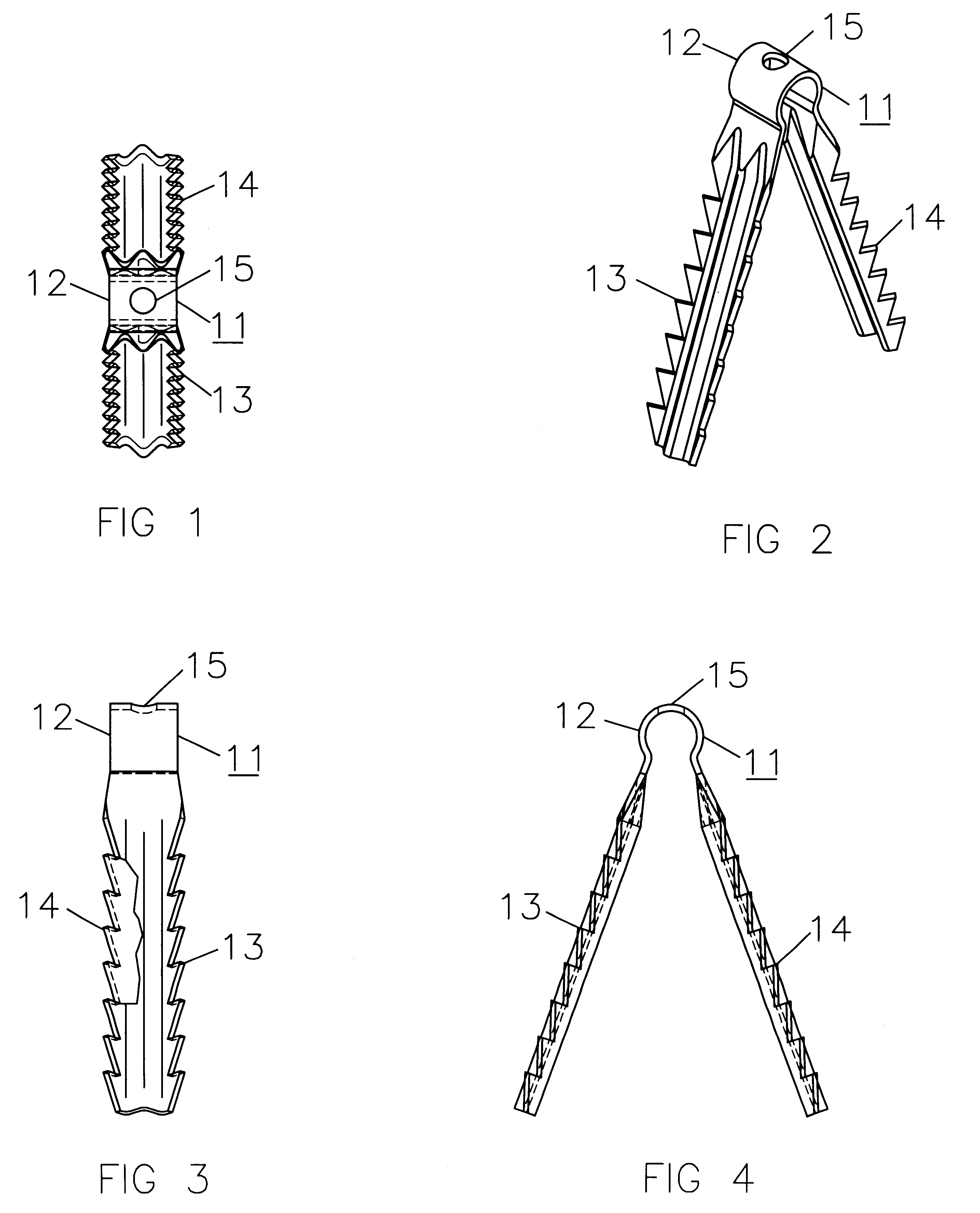
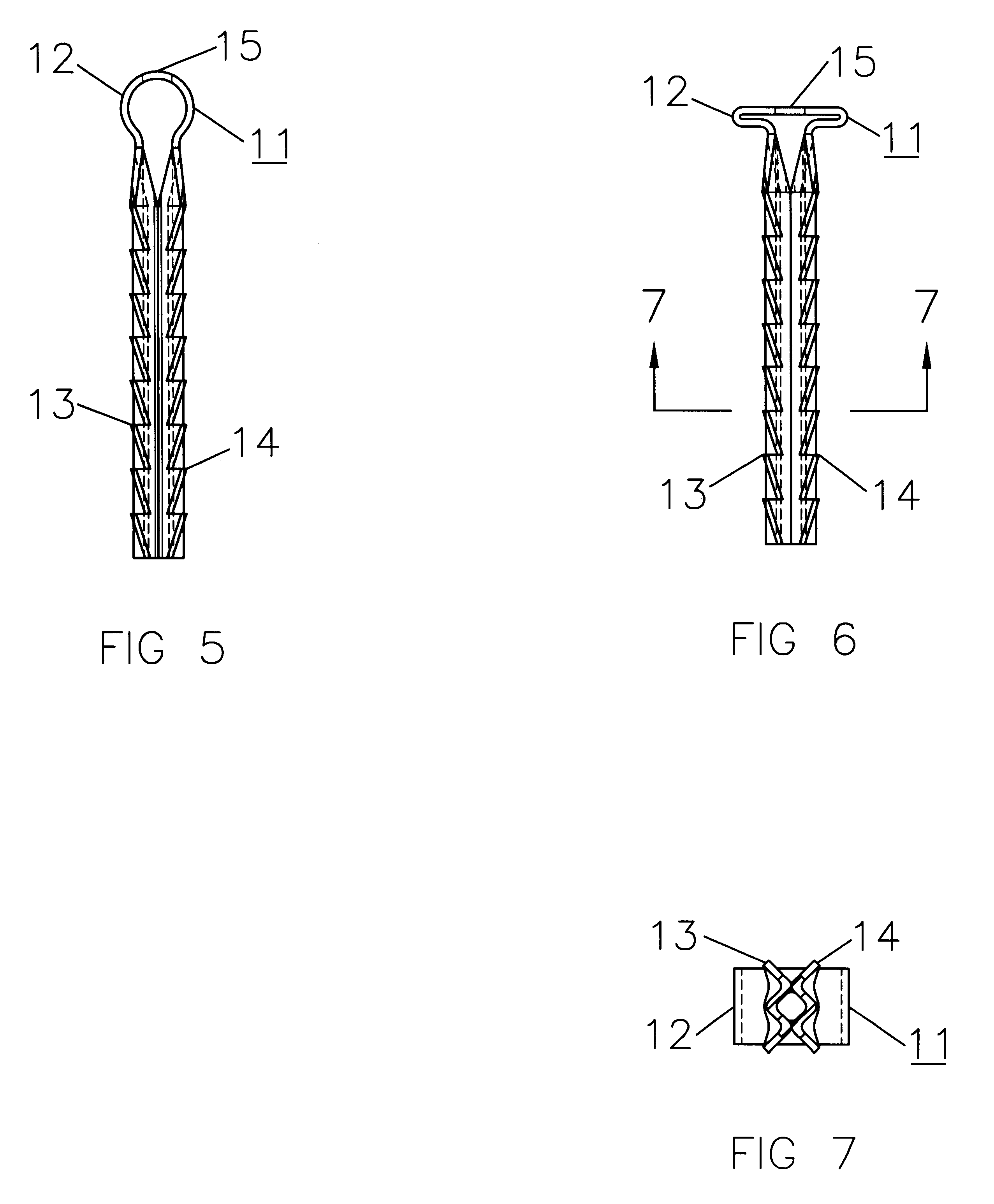
The compact cable anchor for retainment and attachment of cables and tubing n in FIG. 1, FIG. 2, FIG. 3, FIG. 4, FIG. 5, FIG. 6 and FIG. 7, comprises of a one-piece A-shaped rigid body 11, having sufficient thickness, width and length, having the following features: a U-shaped top 12, having front, back and bottom open having sufficient space to receive a cable or tubing, having a W-shaped right side extension 14, being some what parallel to each other having approximate 40 degrees between them with each extension being extended in a downward direction from each side of the U-shaped top 12 forming a A-shaped rigid body 11, each W-shaped extension having a barb surface located at each extreme outer edge of the W-shape having sufficient space and surface as a locking device when pressure is exerted on the outer edge of both extensions causing the extensions to move towards each other causing the space between the extension to become shorter until both the W-shaped left side extension ...


PUM


Abstract

A novel cable anchor for retainment and attachment of cables and tubing which utilizes a one-piece A-shaped rigid body (11) comprising of a U-shaped top (12) having the front, back and bottom open having two extensions one W-shaped left side extension (13) and one W-shaped right side extension (14) both extensions extending in a downward direction having 40 degrees more or less between the extensions. The W-shaped extensions having a barb surface located at the extreme outer surfaces of the W-shape. The U-shaped top (12) having an attachment hole (15) located at the top center. When manual pressure is applied on the outer surfaces of the extensions causing the extensions to move closer towards each other until the extensions are touching each other in the closed position thereby allowing the A-shaped rigid body (11) to be received in a bored hole of a substructure. The U-shaped top (12) may be flattened to facilitate the attachment of a separate cable clip or the like.

Description

BACKGROUND--FIELD OF INVENTIONThis invention relates in general to cable anchors, in particular to a one-piece A-shaped cable anchor which is used for retainment and attachment of phone lines, coax cable (TV cable), cable clips or any other type electrical or non-electrical cable or all types of tubing which needs to be held in a fixed position at various locations during or after the installation of the cable or tubing.BACKGROUND--DESCRIPTION OF PRIOR ARTPrior art cable anchors are very elaborate having multiple elements for securing a cable in a fixed position. In many cases the prior art can't be used to anchor an attached separate cable clip in a fixed position. The difficulties with the prior art cable anchors they are not compact in design and lack the ability to be used as a cable clip with its own anchor an as a cable anchor for attachment of a separate cable clip.Another type self adjusting spring fastener is used for securing one sheet of material to another sheet of mater...

Claims


Application Information

Patent Timeline
IPC IPC(8): F16L3/02F16L3/04
CPCF16L3/04
Inventor JENNINGS, GILBERT M.CARPENTER, VAL
Owner JENNINGS GILBERT M
Why Eureka
Try Eureka