

Pressure-maintaining arrangement
a technology of pressure-maintaining and pressure-regulating valve, which is applied in the direction of machine/engine, fuel injection apparatus, and charge feed system, etc., can solve the problems of high high cost, and fluctuation of pressure in the fuel supply system
- Summary
- Abstract
- Description
- Claims
- Application Information
AI Technical Summary
Benefits of technology
Problems solved by technology
Method used
Image

Examples
Embodiment Construction
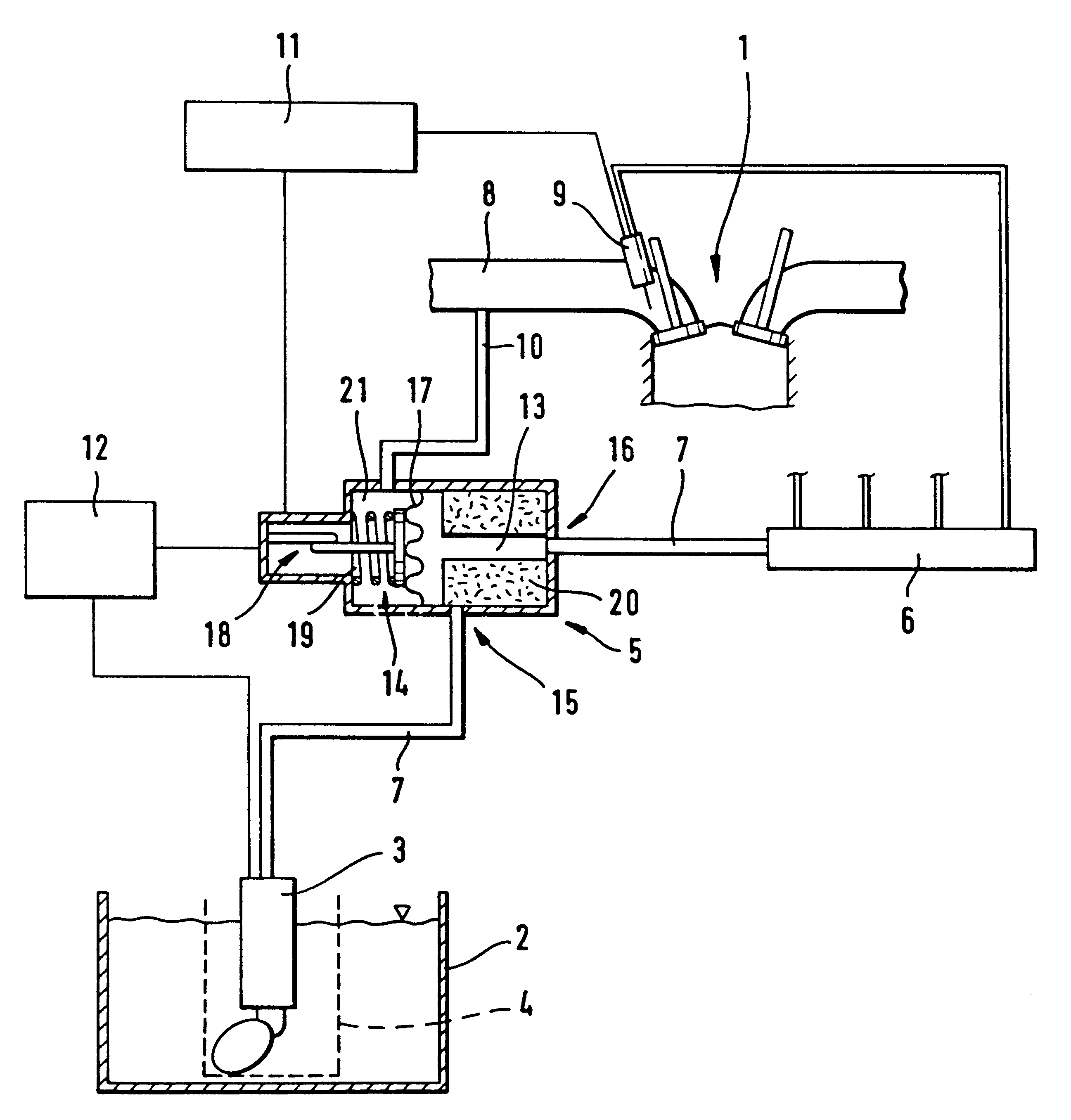
The invention is based on the problem of configuring a pressure-maintaining device of the type mentioned at the beginning such that it is as cost-effective as possible to produce and, by using it, pressure fluctuations in the fuel supply system can largely be avoided.
According to the invention, this problem is solved by the regulating device being designed to produce a central position of the movable wall.
As a result of this configuration, pressure fluctuations in the fuel supply system are largely avoided without using a pressure-regulating valve, since the pressure chamber initially serves briefly as a buffer for insufficiently or excessively delivered fuel. The movable wall serves as a sensor for the regulating device for regulating the fuel pump to meet the demand. The pressure-maintaining device comprises few components, as a result of omitting the pressure-regulating valve, so that it is particularly cost-effective to produce. The fuel supply system according to the invention ...
PUM
 Abstract
Description
Claims
Application Information