Ballast for a discharge lamp with false deactivation detection

a discharge lamp and ballast technology, applied in the direction of electric variable regulation, process and machine control, instruments, etc., can solve the problems of unstable lamp operation, unstable lamp operation, and unstable lamp operation

Inactive Publication Date: 2001-08-28
MATSUSHITA ELECTRIC WORKS LTD
View PDF4 Cites 38 Cited by
  • Summary
  • Abstract
  • Description
  • Claims
  • Application Information

AI Technical Summary

Problems solved by technology

It is known that the discharge lamp will flicker repeatedly when coming near the end of the lamp life, resulting in an unreliable lamp operation as well as posing a stress to the ballast.
However, the scheme allows the lamp to flicker for some time period before ceasing the ballast, leavin

Method used


Image

  • Ballast for a discharge lamp with false deactivation detection
  • Ballast for a discharge lamp with false deactivation detection
  • Ballast for a discharge lamp with false deactivation detection

Examples


Embodiment Construction

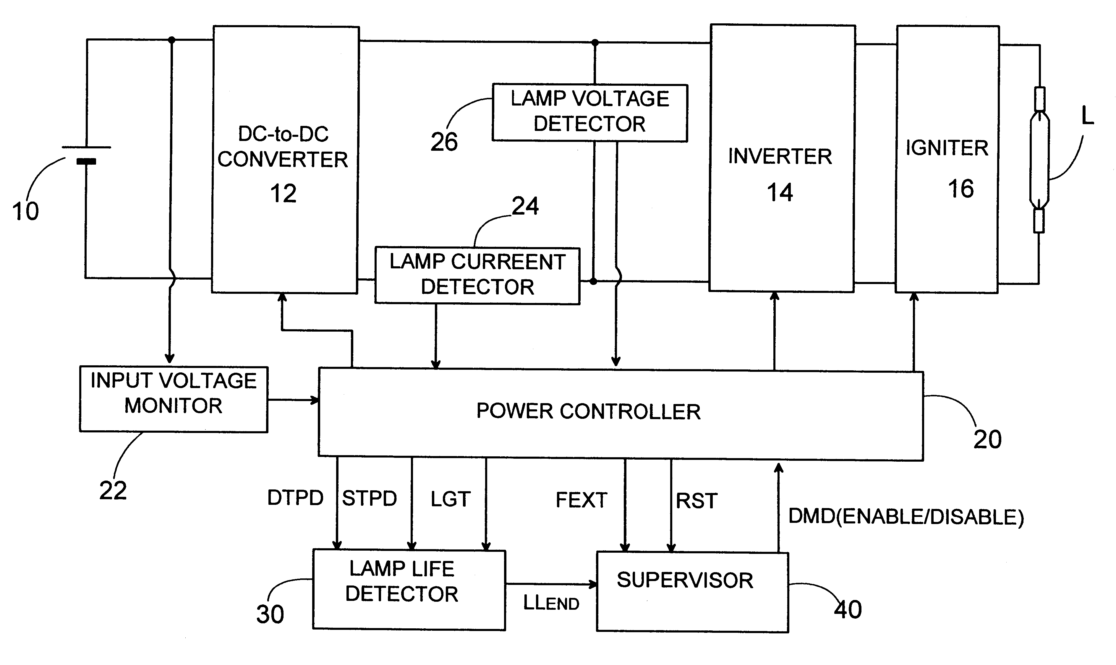
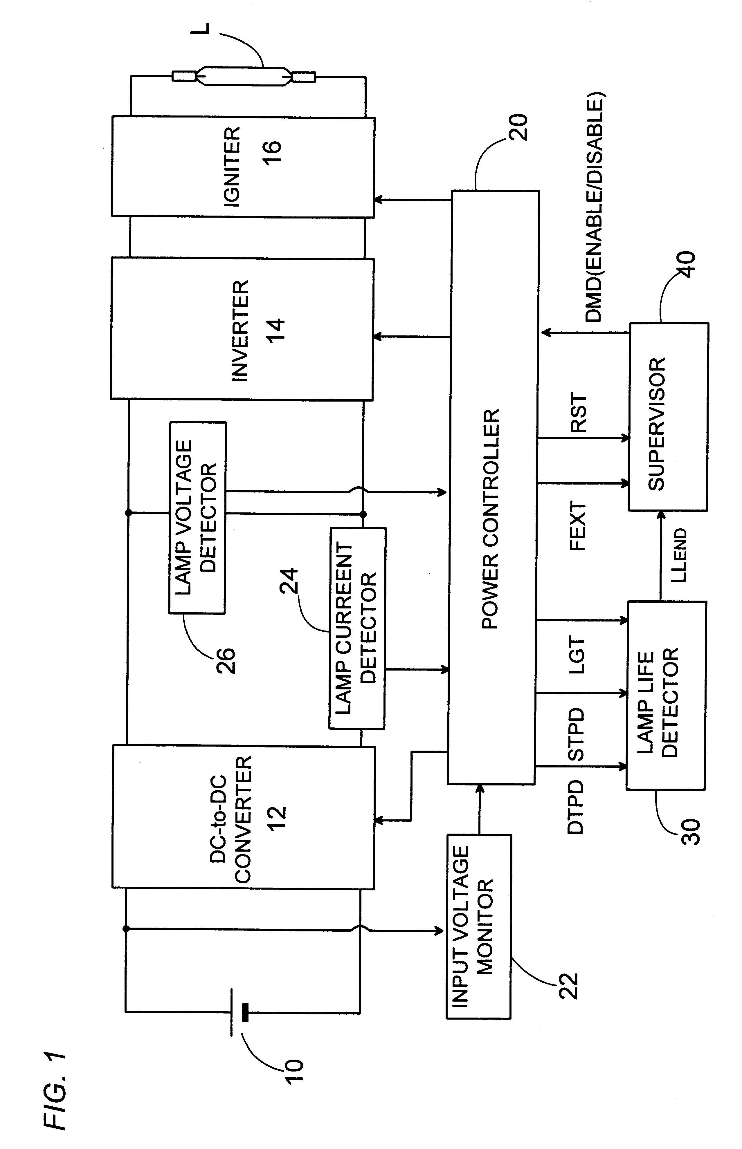
Referring now to FIG. 1, there is shown a ballast in accordance with a preferred embodiment of the present invention. The discharge lamp L is high-intensity discharge lamp such as a metal halide lamp in use, for example, a headlamp of an automobile and a light source for LCD projector. The ballast comprises a DC-to-DC converter 12 which supplies an increased DC voltage from a fixed DC power source 10 such as a battery. Also included in the ballast are an inverter 14 providing an AC voltage from the increased DC voltage, and an igniter 16 providing a high voltage superimposed on the AC voltage from the inverter to ignite the discharge lamp. The DC-to-DC converter 12 is of a fly-back type having a switching element of which duty cycle is regulated by a power controller 20 to provide a boosted DC voltage. The inverter 14 is of a full-bridge type having four switching transistors which are arranged in a bridge and controlled by the power controller 20 to provide AC voltage of about 0 (o...


PUM


Abstract

A ballast for a discharge lamp capable of reliably and successfully detecting the end of the lamp life and ceasing the ballast immediately upon detection of the lamp's life end. The ballast includes a power supply providing from a power source a variable power to the lamp, and a power controller controlling the power supply to apply a high voltage for igniting the lamp and subsequently apply a predetermined power for operating the lamp. A lamp life detector is included in the ballast to detect whether or not the lamp comes to a lamp's life end. Also included in the ballast is a supervisor which issues, upon detection of the lamp's life end, a disable signal prohibiting the power supply from lighting the discharge lamp. The power controller provides a detection period of a limited short time period starting from energization of the ballast such that the lamp life detector can detect the lamp's life end and issue a lamp's life end signal only when there is an extinction of lamp within the detection period, and that the supervisor issues, after the elapse of the detection period, an enable signal permitting the power supply to ignite the discharge lamp if the lamp is extinguished after the elapse of the detection period.

Description

1. Field of the InventionThe present invention relates to a ballast for a discharge lamp, and more particularly to an electronic ballast suitable for operating the discharge lamp utilized as a vehicular headlamp.2. Description of the Prior ArtIt is known that the discharge lamp will flicker repeatedly when coming near the end of the lamp life, resulting in an unreliable lamp operation as well as posing a stress to the ballast. In order to avoid this problem, U.S. Pat. No. 5,880,563 proposes to cease operating the lamp upon detecting the end of the lamp life. In this patent, the lamp flickering is monitored so as to determine the end of the lamp life when the number of the flickering out, i.e., unforced extinction of lamp exceeds a predetermined number. However, the scheme allows the lamp to flicker for some time period before ceasing the ballast, leaving an unstable lamp operation for some time period between the initial lamp extinction and the actual ceasing of the ballast. Thus, u...

Claims


Application Information

Patent Timeline
IPC IPC(8): H05B41/28H05B41/285H05B37/03H05B37/00H05B41/292H05B41/14H05B41/24H05B41/16
CPCH05B37/03H05B41/2925H05B41/2855Y02B20/208H05B47/20Y02B20/00H05B41/14
Inventor KONISHI, HIROFUMINAKAMURA, TOSHIAKIKIDERA, KAZUNORI
Owner MATSUSHITA ELECTRIC WORKS LTD
Why Eureka
Try Eureka