Sliding door hardware assembly and method

a technology for sliding doors and hardware, applied in the field of sliding door hardware, can solve the problems of difficult finishing of the inside edges of the doors proximate the cabinet sides, installation, operation and maintenance problems of sliding doors, and great inconvenience, and achieve the effects of superior functioning cabinet doors, convenient use, and convenient installation

Inactive Publication Date: 2001-09-04
LYON JOHN E
View PDF9 Cites 25 Cited by
  • Summary
  • Abstract
  • Description
  • Claims
  • Application Information

AI Technical Summary

Benefits of technology

In order to overcome these and other problems associated with conventional sliding door cabinet hardware, the present invention was conceived and one of its objectives is to provide cabinet door hardware which is both easy to install and which provides a superior functioning cabinet door.
It is yet another object of the present invention to provide a sliding door hardware assembly and method which can be easily used by inexperienced installers in minimum time.
It is still another objective of the present invention to provide sliding door hardware including a slotted plate which allows a cabinet finisher to quickly, temporarily adjust the door so that all edges are exposed external of the cabinet, without the necessity of totally removing the doors from the cabinet, and then, easily readjusting the door to its normal operational position.
It is a further objective of the present invention to provide metal unshaped spacers and slotted plates which can be uniformly produced and easily adapted to conventional sliding door hardware which will replace wooden fill strips.

Problems solved by technology

These wooden blocks or supports are often unsatisfactory since they may split or be of non-uniform dimensions, causing installation, operation and maintenance problems with the sliding doors.
In addition, as entertainment centers are generally finished with either paint or varnish, the inside edges of the doors proximate the cabinet sides are difficult to finish once the cabinet has been assembled and placed in a home or office.
While the door edges can be finished by removing the doors, this is of great inconvenience as oftentimes the cabinet finishers are not skilled at adjusting the doors whereby the users are left with cabinet doors which do not properly function.

Method used


Image

  • Sliding door hardware assembly and method
  • Sliding door hardware assembly and method
  • Sliding door hardware assembly and method

Examples


Embodiment Construction

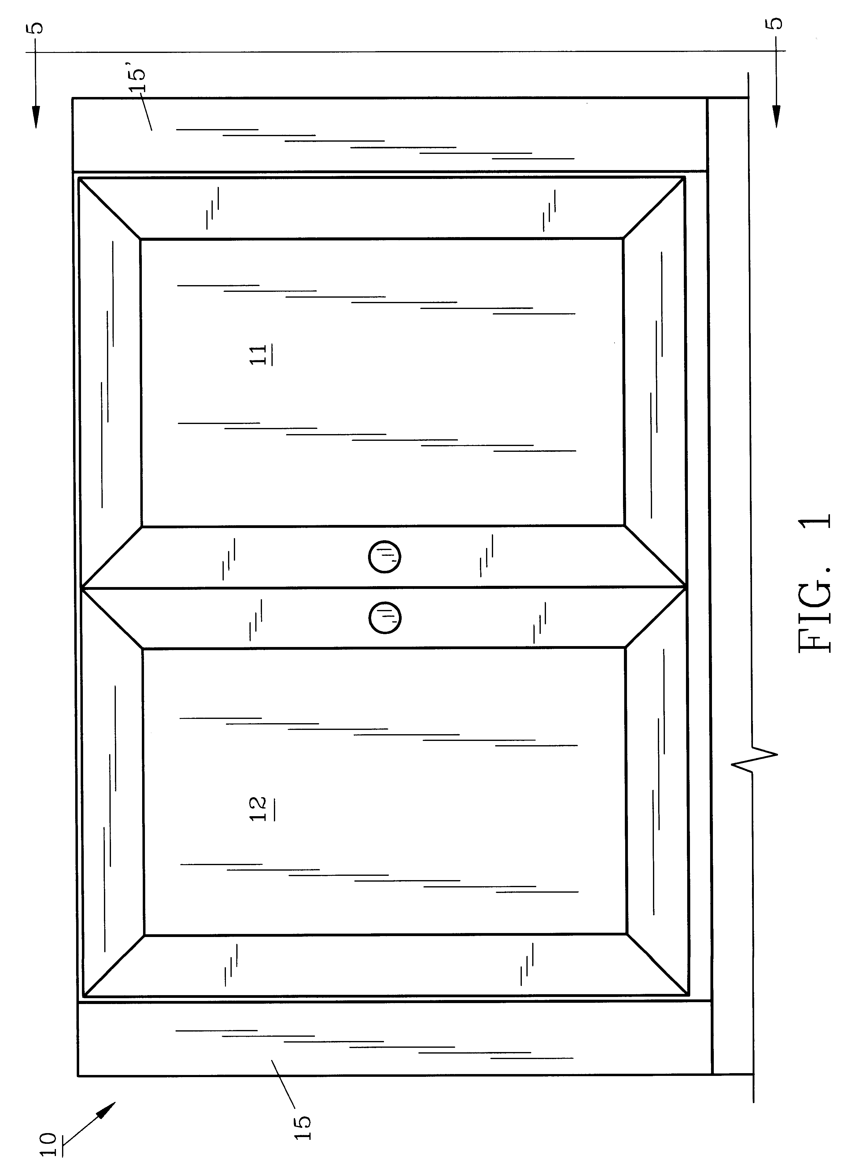
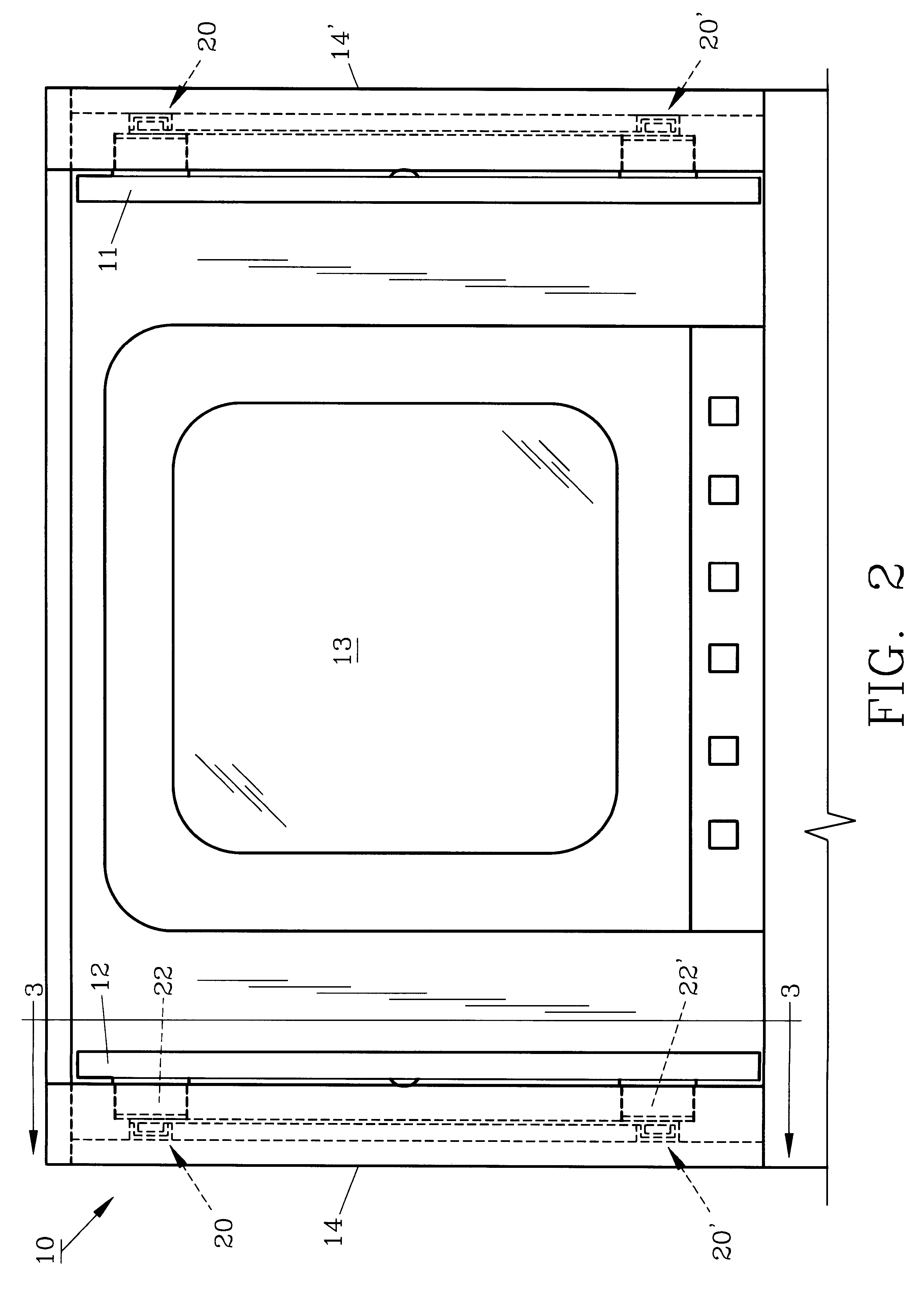
For a better understanding of the invention and its method of use, turning now to the drawings, FIG. 1 demonstrates a partial front elevational view of typical entertainment cabinet 10 with doors 11, 12 closed. Cabinet 10 may be free-standing or may be built into bookshelves or the like. FIG. 2 illustrates cabinet 10 with doors 11, 12 open and withdrawn into cabinet 10 for viewing of television receiver 13. Thus, cabinet doors 11, 12 are opened and slidably positioned within cabinet 10 for convenience and aesthetic purposes. Molding 15, 15' extends along the front of cabinet 10 inwardly from cabinet sidewalls 14, 14' respectively and may be plain or decorative, depending on the specific cabinet design as also seen in FIG. 2.

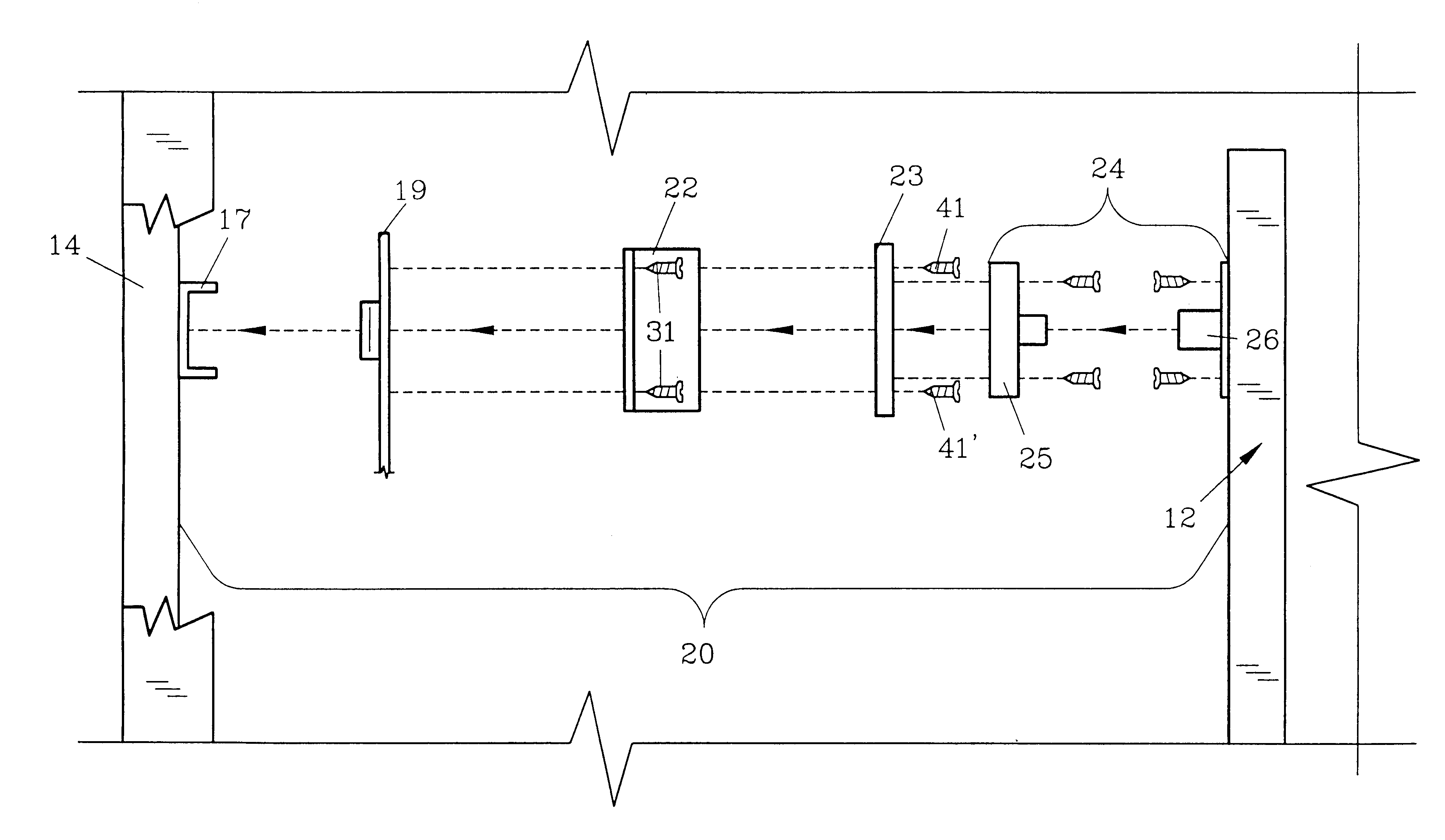
FIG. 3 is taken generally along lines 3--3 as shown in FIG. 2 but with door 12 removed therefrom. As seen, preferred sliding door hardware assembly 20 with tracks 17, 18 are mounted to cabinet sidewall 14 as is conventional and are connected by track arm 19, also...


PUM

PropertyMeasurementUnit
sizeaaaaaaaaaa
dimensionsaaaaaaaaaa
timeaaaaaaaaaa

Abstract

A hardware assembly is provided for cabinet sliding doors as are used with entertainment centers. The hardware assembly includes a u-shaped spacer which is attached to a slotted plate in selective fashion to provide infinite relative positioning. The hardware assembly can be quickly installed and adjusted by inexperienced personnel which is useful in finishing the cabinet and thereafter, daily usage.

Description

1. Field of the InventionThe invention herein pertains to hardware for sliding doors and particularly for large doors as are used with entertainment centers.2. Description of the Prior Art and Objectives of the InventionIn recent years entertainment centers have become popular furniture items for homes, motels, hotels and offices. Entertainment centers are generally large cabinets made of wood or similar materials which will house stereos, cd players, television sets, VCR's and other entertainment equipment. It is important that the entertainment center be closable when not in use yet when opened the doors need to not only fold but retract into the cabinet due to their large size. As a result, folding and sliding door hardware has been used for many years. However, many cabinets have front moldings which extend to reduce the frontal opening. This has required the hardware installers to use wooden blocks or other materials to offset the fixed tracks to accommodate the door to thereby...

Claims


Application Information

Patent Timeline
Patent Type & Authority Patents(United States)
IPC IPC(8): A47B81/06A47B81/00E06B3/50E06B3/32
CPCA47B81/06E06B3/5045Y10T29/4984E05D15/58E05Y2900/212
Inventor LYON, JOHN E.
Owner LYON JOHN E
Why Eureka
Try Eureka