
Method and apparatus for variable bit rate clock recovery

a timing clock and variable bit rate technology, applied in the field of communication network timing clock recovery, can solve the problems of unacceptable link error rate and unexpected network failure, too slow and/or lack of accuracy for variable bit rate applications,

Inactive Publication Date: 2001-09-04
HANGER SOLUTIONS LLC
View PDF31 Cites 58 Cited by
  • Summary
  • Abstract
  • Description
  • Claims
  • Application Information

AI Technical Summary

Problems solved by technology

Failure to detect and correct transmission impairments results in unacceptable link error rates and unexpected network failures.
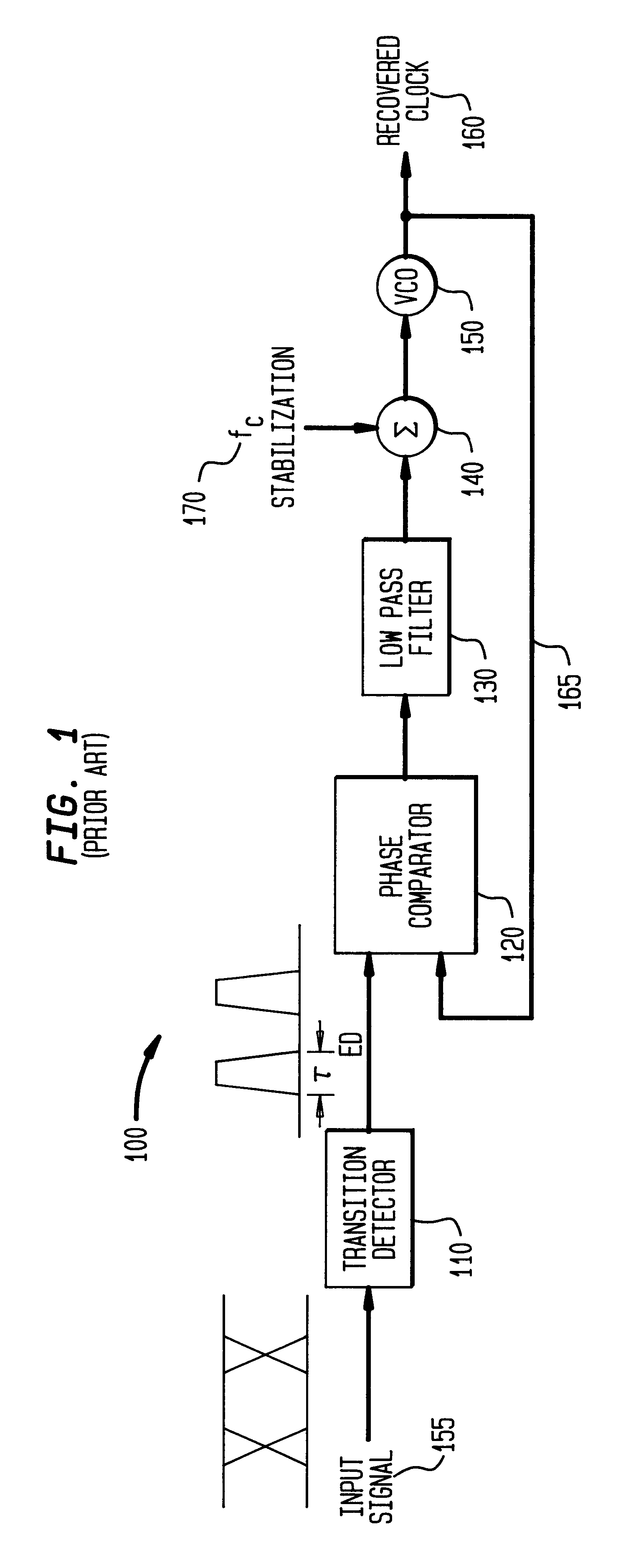
Emerging network technologies, for example photonic switching and Wavelength Division Multiplexing (WDM), however, have enabled complex optical network topologies, where links transport diverse types of traffic, such as Internet Protocol (IP), Asynchronous Transfer Mode (ATM), Fiberchannel, Synchronous Optical Network (SONET), and Gigabit Ethernet.
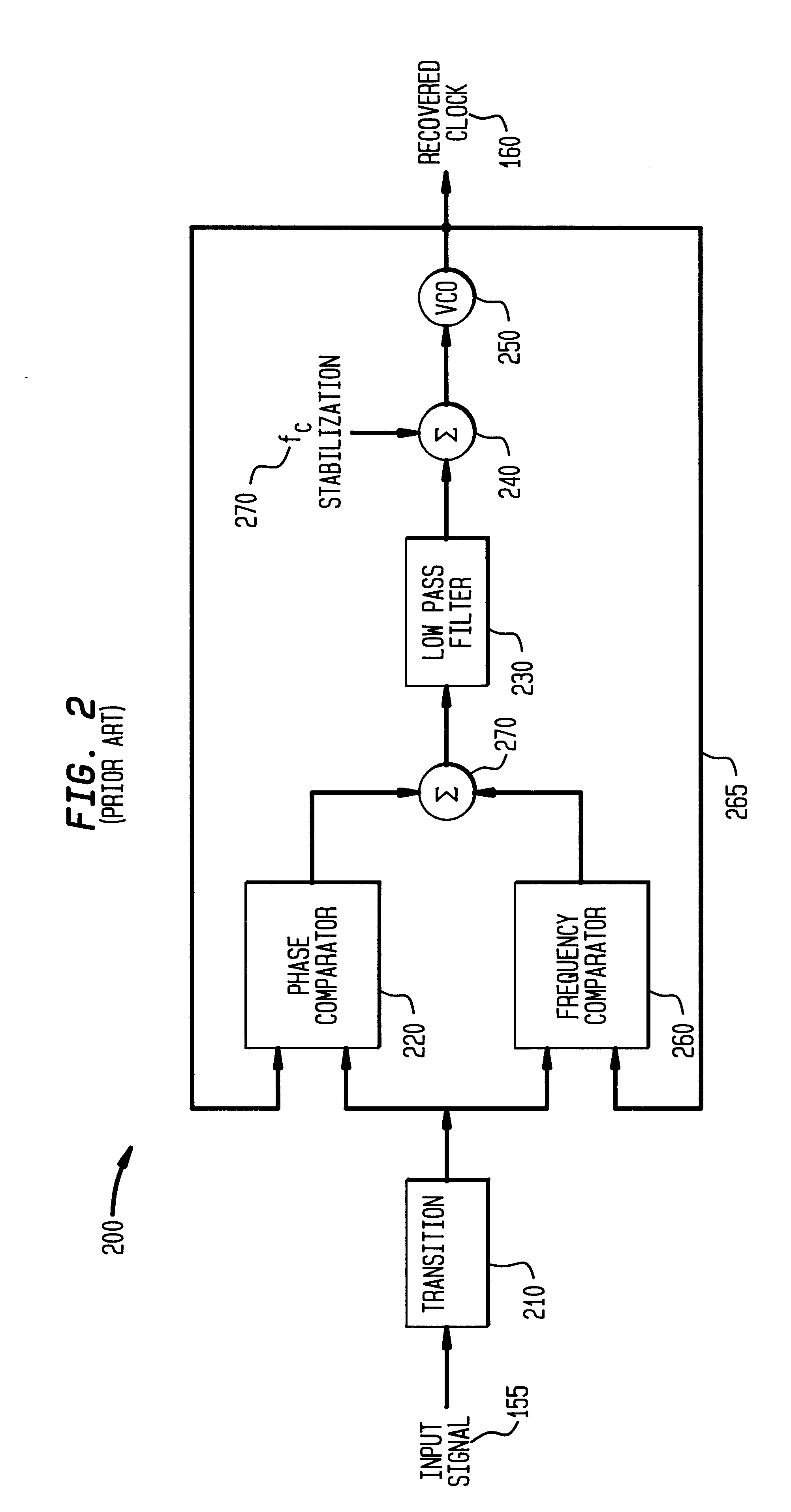
Although various techniques are known for sweeping the center frequency of VCO 250 to determine the bit rate frequency f.sub.bit, these techniques are too slow and / or lack sufficient accuracy for variable bit rate applications.
In addition, the existing techniques cause a clock recovery circuit to readily lock to harmonics and sub-harmonics of the bit rate frequency f.sub.bit.

Method used


Image

  • Method and apparatus for variable bit rate clock recovery
  • Method and apparatus for variable bit rate clock recovery
  • Method and apparatus for variable bit rate clock recovery

Examples


first embodiment

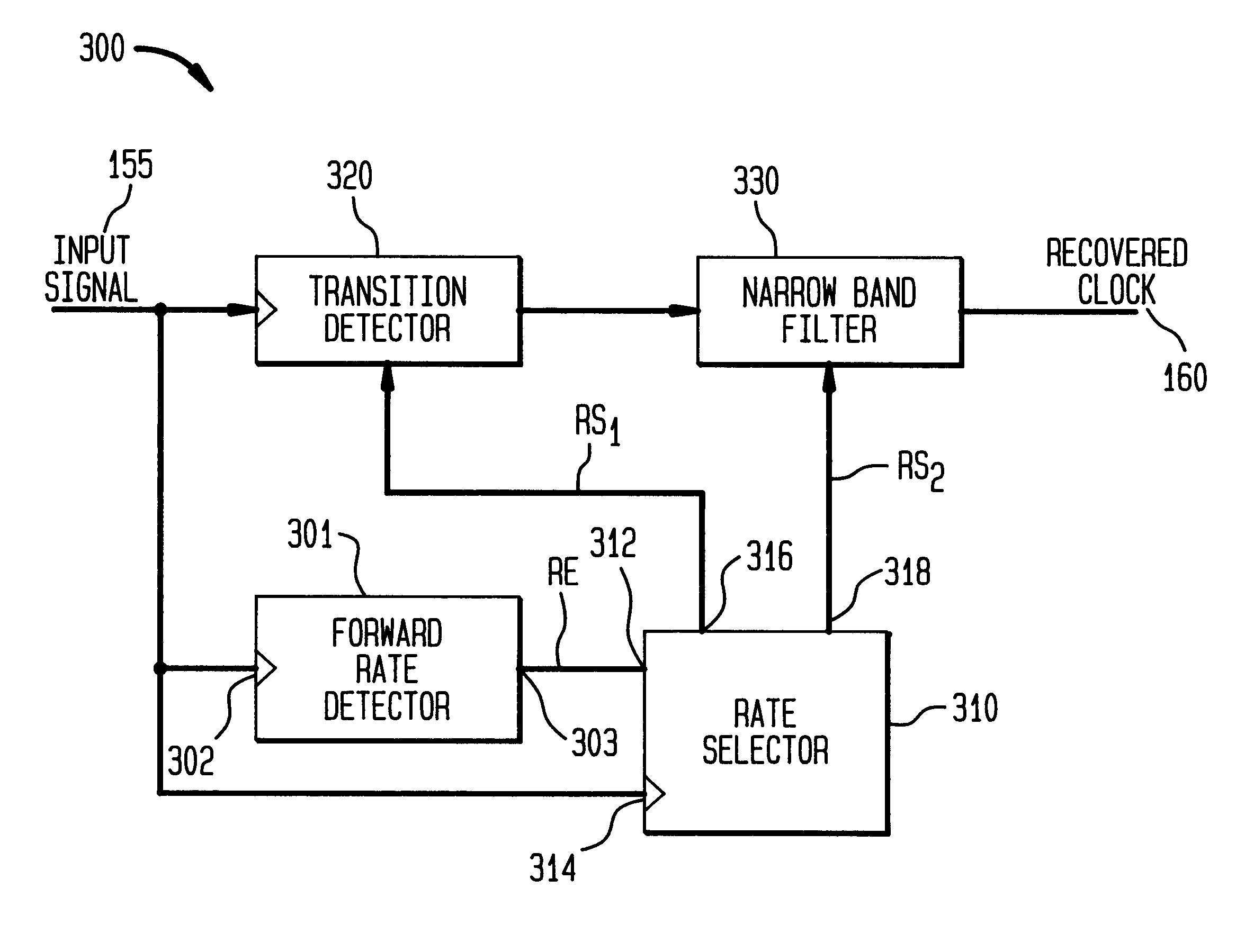
In the first embodiment, time interval generator 810 includes one or more resettable edge triggered delay elements, for example delay elements 510.sub.1 -510.sub.N shown in FIG. 5. As shown in FIG. 9b, in this embodiment, time interval generator 810 generates at output 814 a pulse, which starts after .tau. time has elapsed and is reset by the next transition in input signal 155.

second embodiment

In the second embodiment, time interval generator includes an edge triggered one-shot, which is described below in detail. As shown in FIG. 9c, in this embodiment, time interval generator 810 generates at output 814 a single pulse starting at time .DELTA.t=0, which has duration .tau..

In both embodiments, if time .tau. is set shorter than .tau..sub.bit, as indicated by F, the next transition in input signal 155 occurs at .DELTA.t=.tau..sub.bit after .tau. time has elapsed, and output 826 is set to a low state. If time .tau. is set to a longer duration than .tau..sub.bit, as indicated by S, a subsequent transition in input signal 155 at .DELTA.t=.tau..sub.bit, occurs before .tau. time has elapsed, and output 826 is set to a high state.

There is perfect alignment between the pulse generated at output 814 of time interval generator 810 and input signal 155 when .tau.=.tau..sub.bit, as indicated by A, and a transition in input signal 155 that occurs at .tau..sub.bit overlaps with .tau.. O...


PUM


Abstract

Methods and apparatuses consistent with the present invention recover a clock signal from a variable bit rate data signal by estimating, in the time domain, the bit rate of the data signal, and based on the estimated variable bit rate, determining a center frequency of a narrow-band filter for extracting the clock signal from the data signal. A clock recovery circuit consistent with the present invention extracts a clock signal from a variable bit rate data signal by estimating a minimum time interval between transitions in the data signal, generating a plurality of pulses that correspond respectively to transitions in the data signal, adjusting the duration of each of the pulses based on the estimated minimum time interval and inputting into a narrow-band filter the adjusted pulses, determining a center frequency of the narrow-band filter based on the estimated minimum time interval, and extracting in the narrow-band filter the clock signal from the adjusted pulses.

Description

1. Field of the InventionThe present invention relates generally to recovering timing clock of signals in communication networks, and more particularly, to methods and apparatuses for recovering timing clock of variable bit rate signals in communication networks.2. Background of the ArtHigh reliability networks, which handle diverse types of traffic from diverse sources, monitor and manage in the time domain the quality of digital transmission. Failure to detect and correct transmission impairments results in unacceptable link error rates and unexpected network failures. Hence, networks must extract from a stream of transmitted data a clock signal to perform the necessary measurements and correct for inevitable transmission degradation.An extracted clock signal is necessary to perform time domain measurements, such as eye-pattern opening and timing jitter. The extracted clock signal is also essential for distinguishing the individual data bits in the transmitted data stream prior to...

Claims


Application Information

Patent Timeline
Patent Type & Authority Patents(United States)
IPC IPC(8): H04L25/02H04L7/027H04L7/02H04L7/033
CPCH04L7/027H04L25/0262H04L7/0334H04L7/033
Inventor BANWELL, THOMAS C.CHEUNG, NIM K.
Owner HANGER SOLUTIONS LLC
Learn More