Automated oil changing system

a technology for automatic oil change and engine, which is applied in the direction of machines/engines, liquid handling, packaging goods types, etc., can solve the problems of inconvenience, many are stranded at service centers, and individuals must still waste time for routine maintenance on their vehicles

Inactive Publication Date: 2001-09-11
CANNON DAVID G
View PDF22 Cites 25 Cited by
  • Summary
  • Abstract
  • Description
  • Claims
  • Application Information

AI Technical Summary

Problems solved by technology

Even though society has become increasingly efficient, individuals must still waste time for routine maintenance on their vehicles.
Many are stranded at service centers while waiting for the maintenance to be finished.
Others are inconvenienced by resorting to a courtesy van or finding another source of transportation to work while the vehicle is being serviced.
These individuals not only waste time driving to the service center, but are also confined ...

Method used


Image

  • Automated oil changing system
  • Automated oil changing system
  • Automated oil changing system

Examples


Embodiment Construction

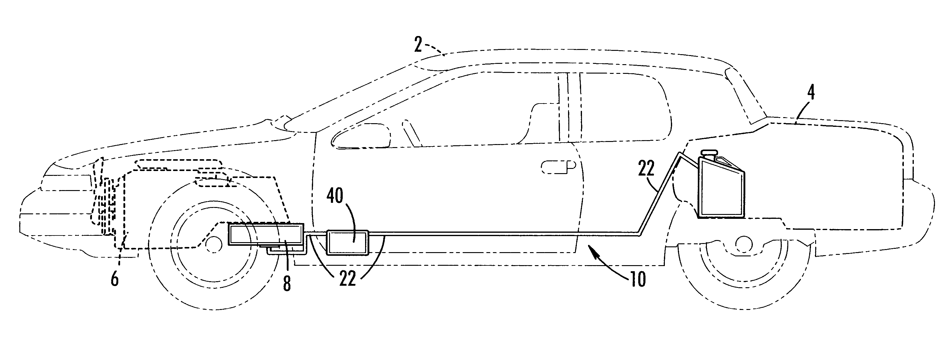
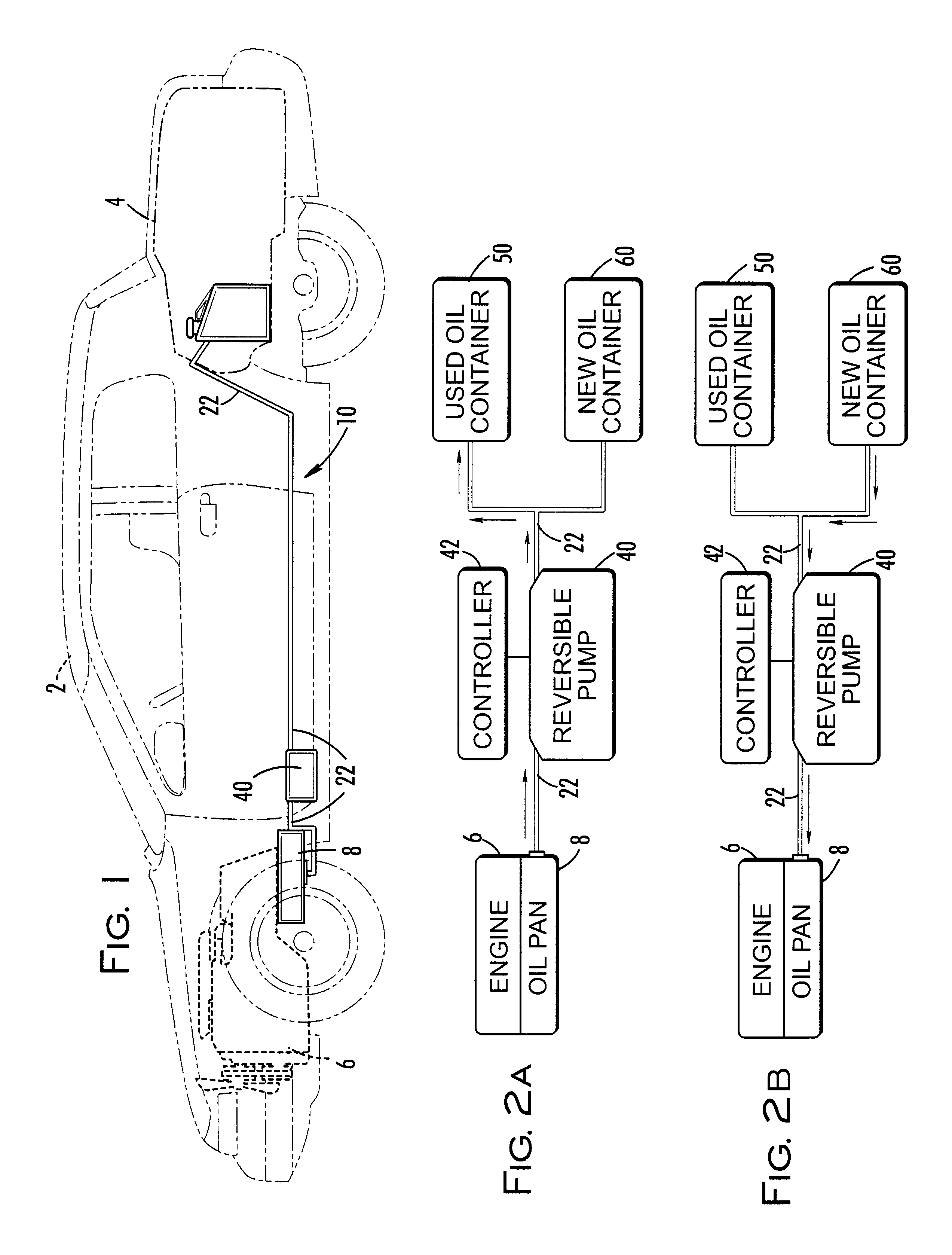
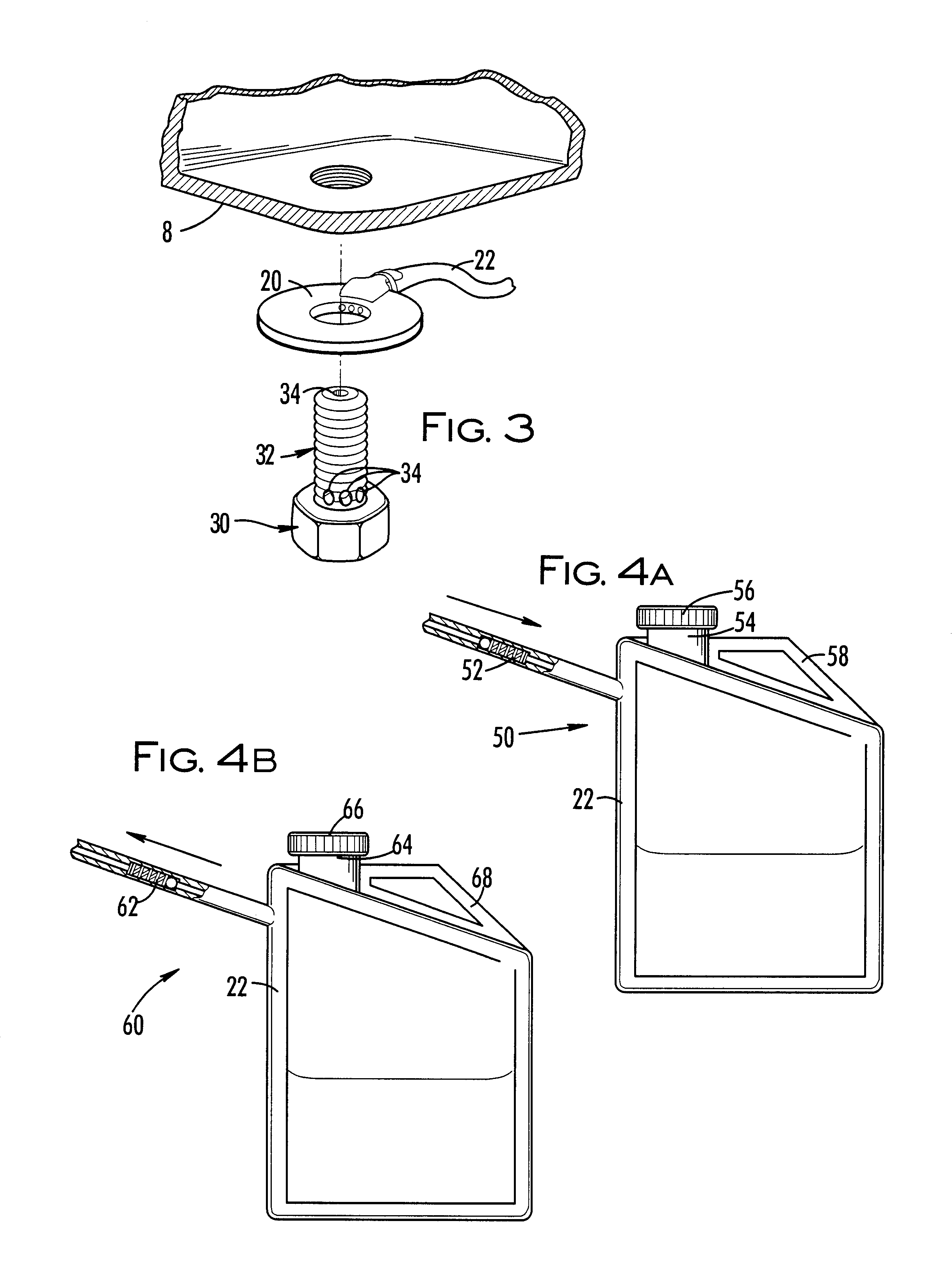
Referring now to the figures, the present invention is an automated system for changing the motor oil in an engine. The system, generally referred to by reference number 10, comprises a drain plug 30 coupled with tubing 22 which extends to a reversible pump 40. A used oil container 50 and a new oil container 60 are in fluid communication with pump 40 using tubing 22. It will be clear to those skilled in the art that system could be used for replacing any type of fluid in an engine.

Drain plug 30 with coupling 20 and tubing 22 allow fluid communication between oil pan 8 and both used oil container 50 and new oil container 60. Drain plug 30 has at least one channel 32 positioned to allow fluid communication between plug 30 and coupling 20. Although only one channel is needed, preferably drain plug 30 has a plurality of channels to allow fluid communication with coupling 20. As illustrated in FIG. 3, coupling 20 is mounted to plug 30 so that coupling 20 collects oil flowing from channel...


PUM

PropertyMeasurementUnit
Flow rateaaaaaaaaaa

Abstract

An automated system for changing the motor oil in an engine. The system includes a drain plug having a plurality of channels coupled with tubing that extends to a reversible pump. Tubing extends from the pump to both a used oil container and a new oil container. Check valves positioned at the entrance of each container restrict flow so the oil can flow only to the used oil container and only flows from the new oil container. Preferably, both containers are located in the trunk of the vehicle for easy access. In use, the pump is engaged to draw the used motor oil from the engine into the used oil container. Next, the pump is reversed to draw fresh oil from the new oil container into the engine.

Description

1. Field of the InventionThe present invention relates to changing the motor in a vehicle. In particular, the present invention relates to automated systems for changing motor oil in an engine.2. Discussion of BackgroundEven though society has become increasingly efficient, individuals must still waste time for routine maintenance on their vehicles. Many are stranded at service centers while waiting for the maintenance to be finished. Others are inconvenienced by resorting to a courtesy van or finding another source of transportation to work while the vehicle is being serviced. These individuals not only waste time driving to the service center, but are also confined to the dealer's service schedule. For those managing the maintenance of a rental or service fleet, this inconvenience can also be a logistical problem.Although many "quick lubes" business have been established to perform quick oil changes, these businesses do not make house calls; in other words, individuals employing t...

Claims


Application Information

Patent Timeline
IPC IPC(8): F01M11/04
CPCF01M11/0458F01M2011/0466
Inventor EVANS, LARRY D
Owner CANNON DAVID G
Why Eureka
Try Eureka