
Internal air pump for inflatables

Inactive Publication Date: 2001-09-11
INTEX RECREATION
View PDF19 Cites 73 Cited by
  • Summary
  • Abstract
  • Description
  • Claims
  • Application Information

AI Technical Summary

Benefits of technology

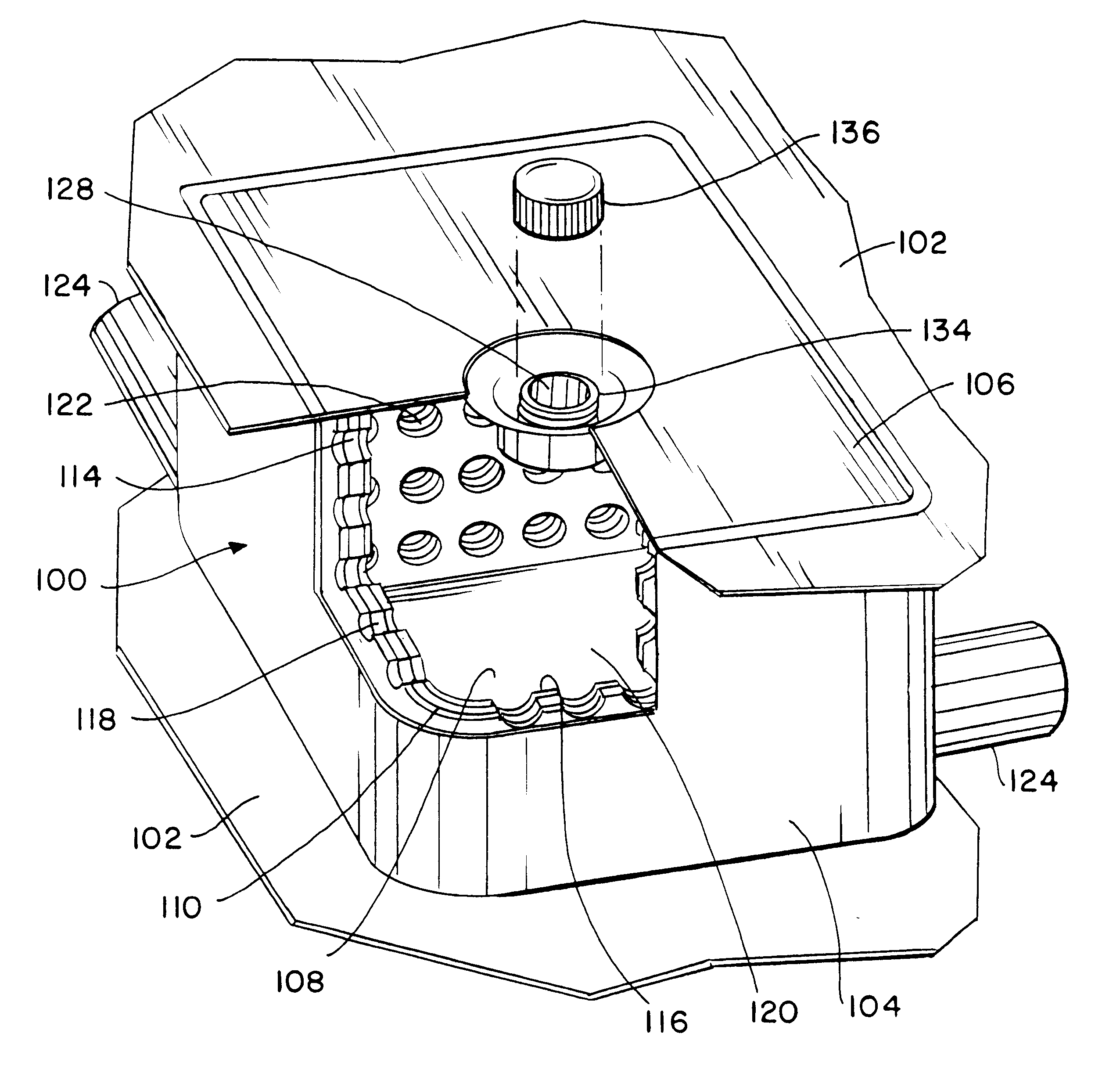
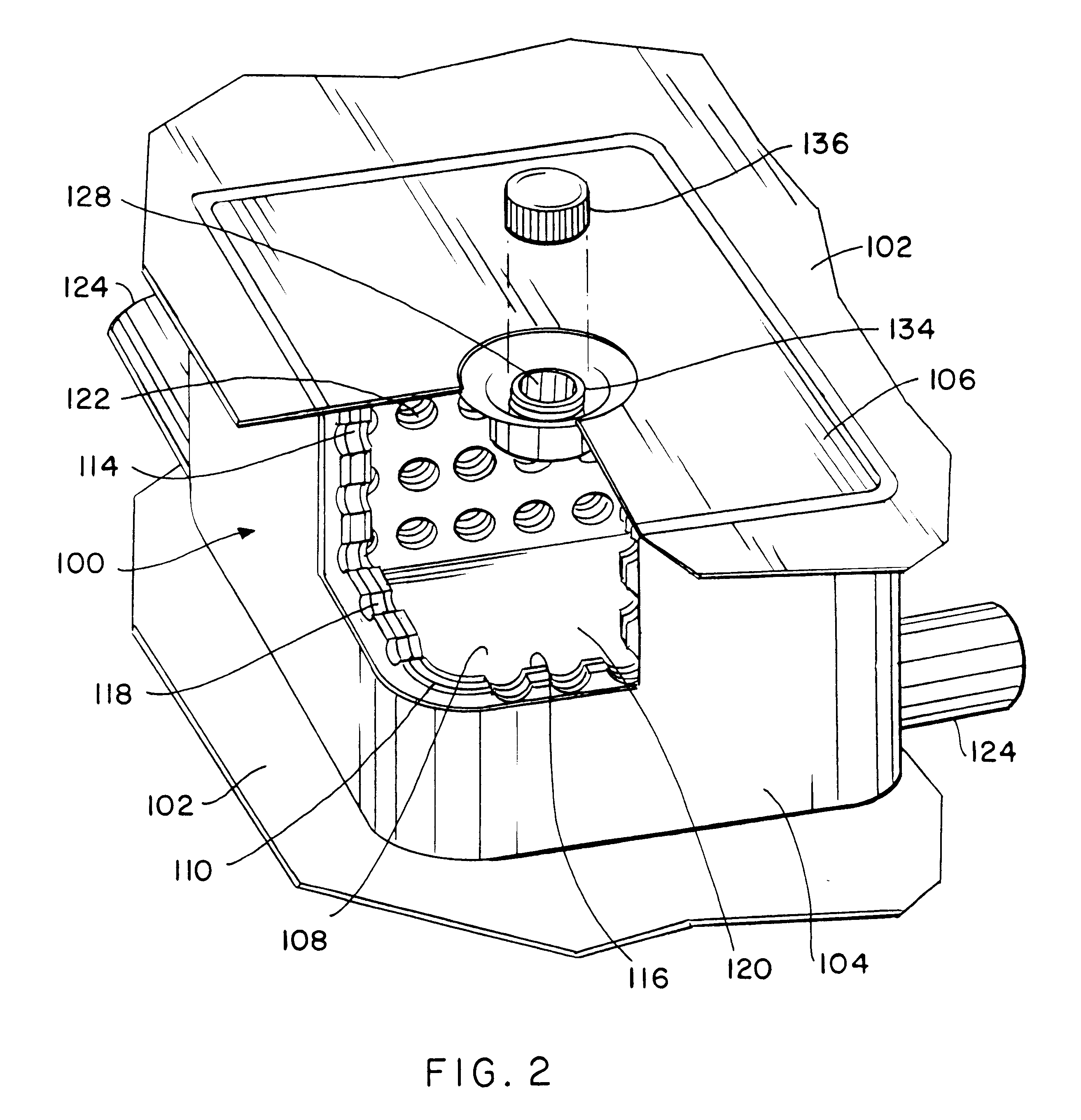
The present invention is generally directed to an air pump mounted internal to an inflatable device for injecting air therein. The inventive air pump is lightweight and easily packaged within the inflatable device and can be used to inflate the device to a desired air pressure. In its most fundamental embodiment, the internal air pump comprises a construction including an outer shell layer having a continuous sidewall, a roof layer and a floor layer for defining an enclosed inner pump chamber. An inner sandwich layer is positioned adjacent to the outer shell layer and includes a resilient component. At least one air intake valve is mounted within the roof layer for admitting air into the inner pump chamber. Further, one or more exhaust ducts are mounted in the outer shell layer for discharging air from the inner pump chamber to an inflatable device. An external force applied to the air pump forces air from the inner pump chamber to the exhaust ducts. The resilient component enables the air pump to self-adjust after the external force is removed.
In a preferred embodiment, a passageway is formed between the outer shell layer and the inner sandwich layer. Additionally, a plurality of perforations are formed through the sandwich layer. The combination of the plurality of perforations and the passageway provide an alternative pathway for exhausting air from the inner pump chamber to the exhaust ducts when the external force is applied to the air pump. This alternative pathway is in addition to the direct pathway that exists from the inner pump chamber directly to the exhaust ducts via the perforations. Thus, exhausting of air from the inner pump chamber is maximized which improves the efficiency of the air pump in charging the inflatable device with air. Additionally, the preferred embodiment includes a threaded cap for mating with the top of the threaded air intake port mounted within the roof layer of the air pump. The cap ensures that air leakage from the inner pump chamber through the air intake valve flap will be prevented. Finally, most of the components of the preferred embodiment of the internal air pump are comprised of Polyvinylchloride (PVC) which is lightweight, flexible and robust. Other suitable polymeric materials can also be used.

Problems solved by technology

Inflatable devices and objects known in the past were often comprised of heavy gauge plastic, rubberized and other synthetic materials which were not convenient to inflate and transport.

Method used


Image

  • Internal air pump for inflatables
  • Internal air pump for inflatables
  • Internal air pump for inflatables

Examples


Embodiment Construction

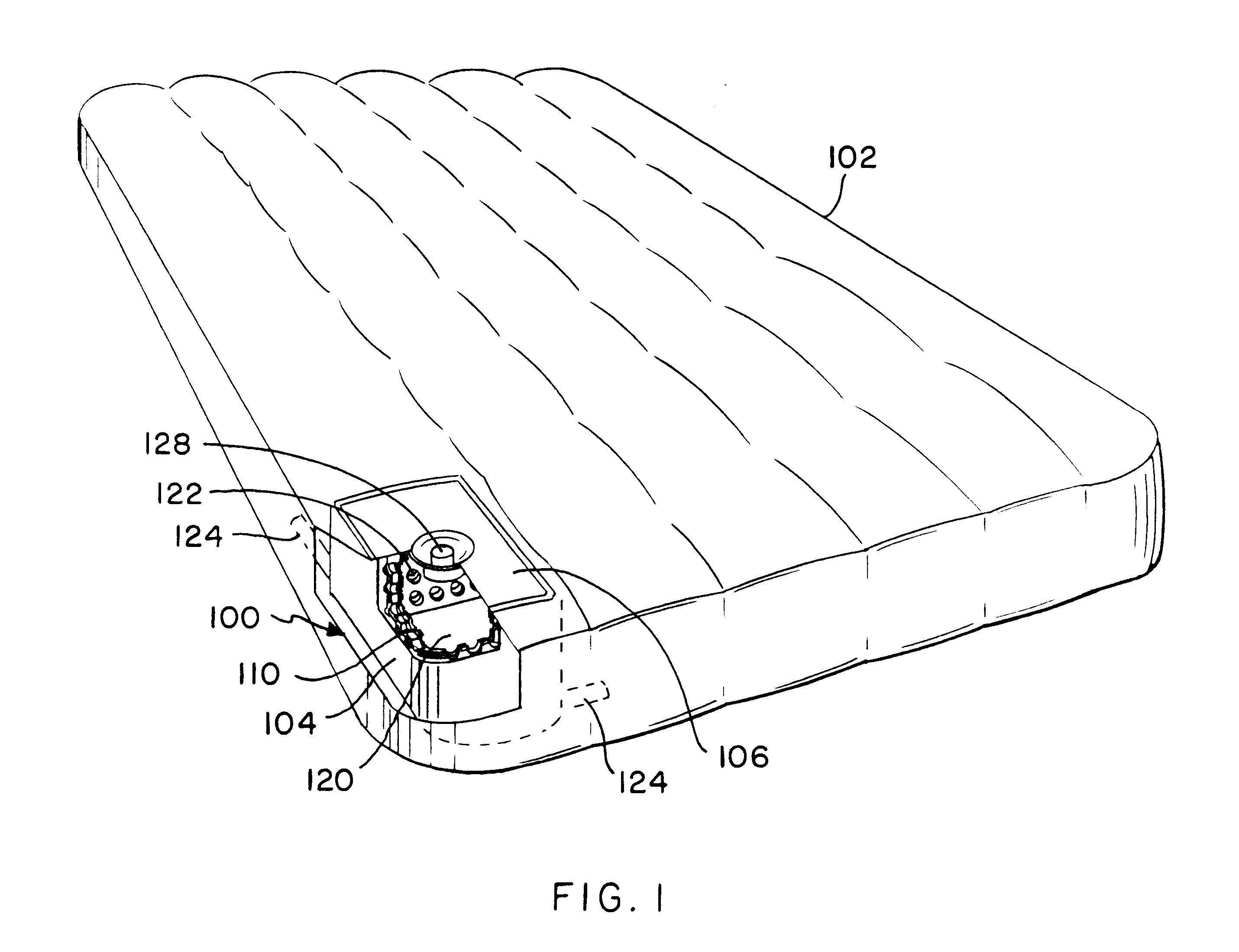
The present invention is an internal air pump 100 for use in charging inflatables, i.e., an inflatable device 102 with air and method therefore as shown in FIGS. 1-6 herein. The inflatable device 102 can include any of various inflatables which must be charged with air or other gas in order to be functional. In the preferred embodiment of the present invention, the inflatable device 102 is illustrated as an air mattress. However, the inflatable device 102 could also be an article of air inflatable furniture, an air inflatable watercraft, or an above-the-ground swimming pool having inflatable sides.

It is significant to note that the internal air pump 100 of the present invention is positioned within, i.e., incorporated within, the inflatable device 102 as is shown in FIG. 1. Further, the air pump 100 can be located within the inflatable device 102 so as not to interfere with the functionality of the inflatable device 102. For example, the air pump 100 shown in FIG. 1 is positioned in...


PUM


Abstract

An internal air pump for charging inflatables with air and method therefore is disclosed which is directed to an air pump mounted internal to an inflatable device for injecting air therein. The inventive air pump is a thin-walled, lightweight, highly elastic, flexible plastic construction which is easily packaged within the inflatable device and can be used to inflate the device to a desired air pressure. In its most fundamental embodiment, the internal air pump comprises a construction including an outer shell layer having a continuous sidewall, a roof layer and a floor layer for defining an enclosed inner pump chamber. An inner sandwich layer is positioned adjacent to the outer shell layer and includes a resilient component. At least one air intake valve is mounted within the roof layer for admitting air into the inner pump chamber. One or more exhaust ducts are mounted in the outer shell layer for discharging air from the inner pump chamber to an inflatable device. An external force applied to the air pump forces air from the inner pump chamber to the exhaust ducts. The resilient component enables the air pump to self-adjust after the external force is removed.

Description

1. Field of the InventionThe present invention relates to air pumps. More specifically, the present invention relates to methods and apparatus for an internal air pump for use with inflatables, i.e., inflatable devices, such as an air mattress, and which includes a thin-walled, highly elastic, lightweight, robust, durable, flexible plastic construction which is self-adjusting and highly reliable against failure.2. Description of the Prior ArtThe prior art is directed to methods and apparatus for internal air pumps for use with inflatable devices such as, for example, air mattresses. The use of inflatable devices fabricated from modern lightweight plastics has increased in recent years. Inflatable devices are now typically found in camping equipment, residential and beach air inflatable furniture, swimming pool lounging equipment, watercraft and the like. Therefore, advances in means for inflating the myriad of inflatable devices has occurred.Inflatable devices and objects known in t...

Claims


Application Information

Patent Timeline
IPC IPC(8): A47C27/08F04B45/02F04B33/00F04B45/00
CPCA47C27/081F04B45/02F04B33/00A47C27/084
Inventor SAPUTO, RICHARD A.LIN, HUA HSIANG
Owner INTEX RECREATION
Learn More