Hand-held epilating device

a technology of epilating device and hand, which is applied in the field of hand-held epilating device, can solve the problems of insufficient plucking efficiency

Inactive Publication Date: 2001-09-11
MATSUSHITA ELECTRIC WORKS LTD
View PDF7 Cites 19 Cited by
  • Summary
  • Abstract
  • Description
  • Claims
  • Application Information

AI Technical Summary

Problems solved by technology

That is, the hair plucking is made to limited portions within the area of the skin covered by the rotary cylinder, posing insufficient plucking efficiency.

Method used


Image

  • Hand-held epilating device
  • Hand-held epilating device
  • Hand-held epilating device

Examples


Embodiment Construction

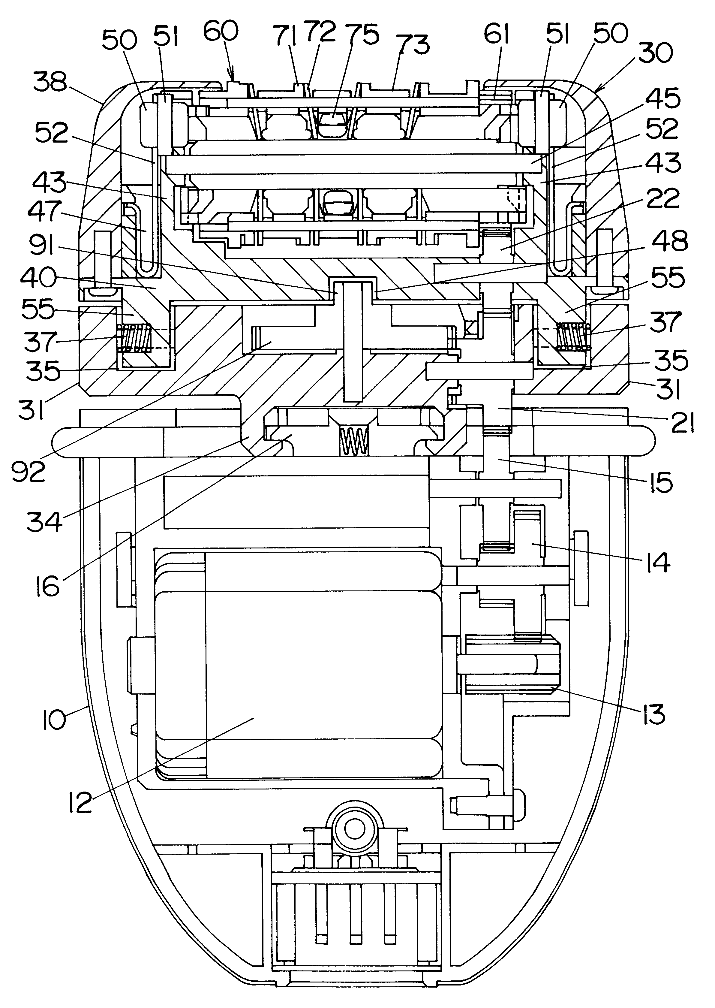
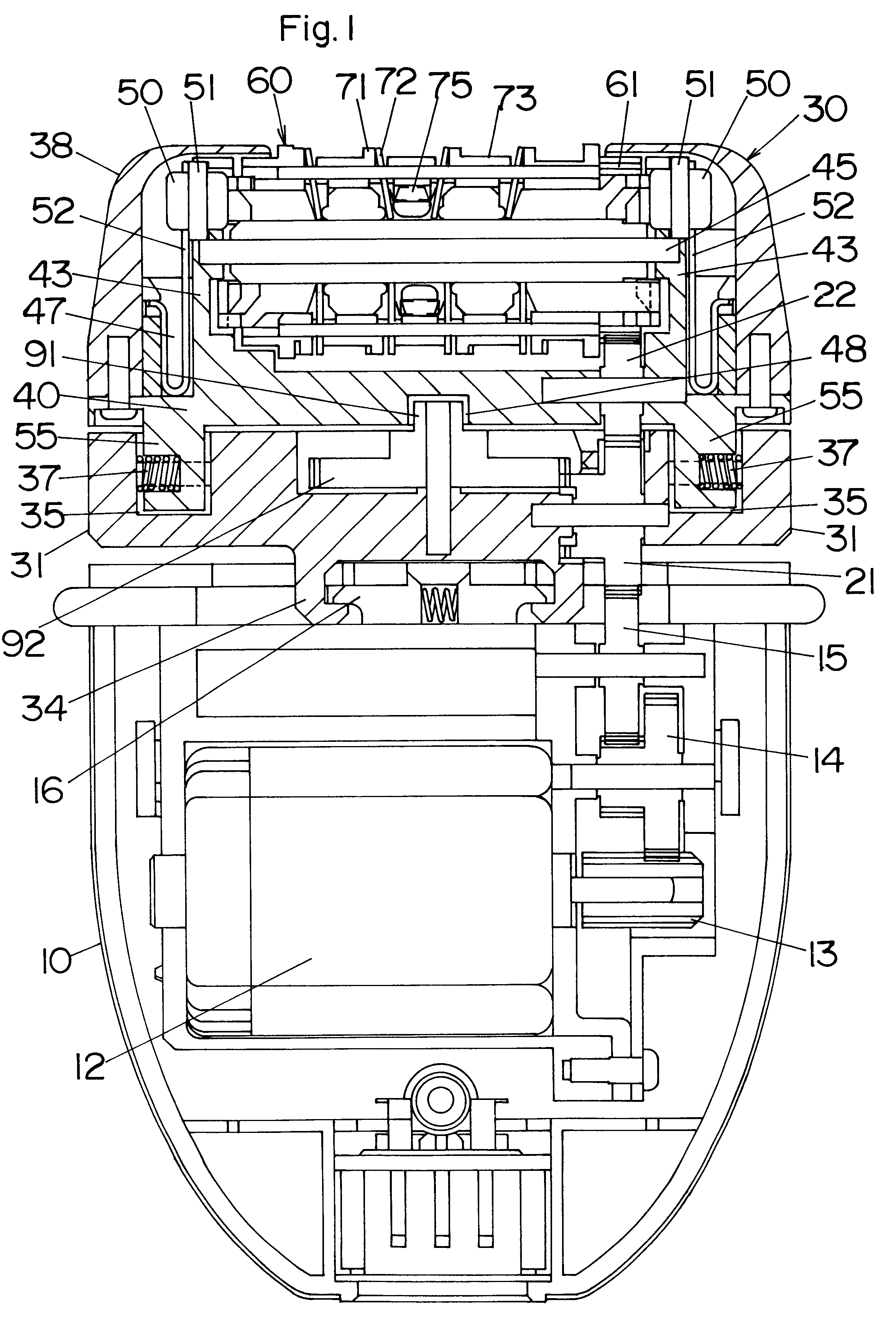
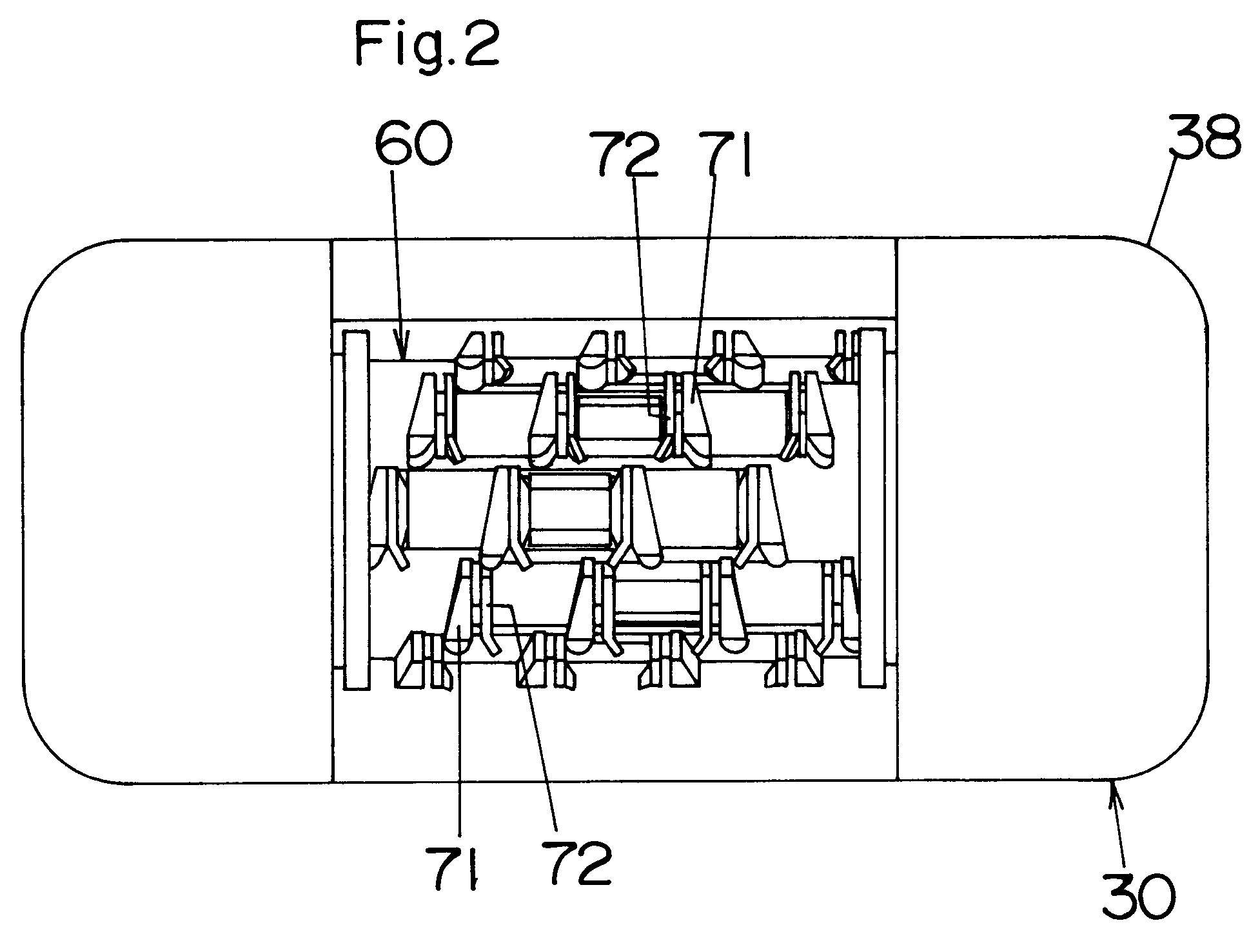
Referring now to FIGS. 1 to 3, there is shown a hand-held epilating device in accordance with a first embodiment of the present invention. The epilating device has a housing 10 to be grasped by a user's hand and an epilator head 30 detachably mounted on top of the housing 10. The housing 10 has an upright axis and accommodates an electric motor 12 and a set of driving gears 13 to 15 for providing a source of operating the epilator head 30. The epilator head 30 is composed of a base 31, a head frame 40, a head cover 38 and a plucking cylinder 60. The base 31 is provided on its bottom with hooks 34 for detachable engagement with latches 16 on top of the housing 10. The head frame 40 is supported on the base 31 and carries the plucking cylinder 60 as well as the head cover 38. As best shown in FIG. 3, the base 31 is of two-parts structure having a main base 32 and a sub base 33 which are assembled together with a first driven gear 21 interposed therebetween. The first driven gear 21 co...


PUM


Abstract

A hand-held epilating device capable of increasing plucking efficiency. The epilating device has a housing to be grasped by a hand of a user, and a plucking cylinder carrying at least one set of pinching elements for catching and pinching body hairs therebetween. The plucking cylinder has a longitudinal axis and is driven to rotate about the longitudinal axis to pluck the body hairs from the user's skin. The plucking cylinder is supported to the housing so as to effect a periodical movement relative to the housing within a plane parallel to the longitudinal axis. Thus, the area of the skin covered by the plucking cylinder can have increased chances of being in contact with the pinching elements as the pinching elements move periodically relative to the skin together with the plucking cylinder, thereby improving the plucking efficiency.

Description

1. Field of the InventionThe present invention is directed to a hand-held epilating device, more particularly to such a device having a plucking cylinder which is driven to rotate for plucking body hairs.2. Description of the Prior ArtU.S. Pat. No. 5,857,903 discloses a hand-held epilating device having a rotary cylinder which is provided with sets of pinching elements for pinching body hairs therebetween. The rotary cylinder is driven to rotate about its longitudinal axis to pluck the pinched hairs. The rotary cylinder is supported to a head member fixed to a housing grasped by the hand of a user so that the pinching elements on the rotary cylinder traces only a circular path around the rotary cylinder and do not move in the other directions relative to a skin surface of the user when the rotary cylinder is held against a fixed area of the skin surface. Since the sets of the pinching elements are arranged in a spaced relation from each other on the rotary cylinder, the hairs at the...

Claims


Application Information

Patent Timeline
Patent Type & Authority Patents(United States)
IPC IPC(8): A45D26/00
CPCA45D26/0023
Inventor INOUE, TOMOYUKISUEYOSHI, HIDEKAZUIWASAKI, JYUZAEMON
Owner MATSUSHITA ELECTRIC WORKS LTD
Why Eureka
Try Eureka