System for improved memory cell access

a memory cell and access technology, applied in the field of system for improving memory cell access, can solve problems such as read destructivization

Inactive Publication Date: 2001-09-11
MICRON TECH INC
View PDF21 Cites 13 Cited by
  • Summary
  • Abstract
  • Description
  • Claims
  • Application Information

AI Technical Summary

Benefits of technology

In one embodiment of the present memory access system, a voltage booster is used to increase the column select signal voltage applied to the passgate to avoid a voltage drop across the passgate during memory cell read and write operations.

Problems solved by technology

Additionally, each cell is rewritten upon a read instruction, since the reads are destructive without the immediate rewrite.

Method used


Image

  • System for improved memory cell access
  • System for improved memory cell access
  • System for improved memory cell access

Examples


Embodiment Construction

In the following detailed description of the preferred embodiment, references are made to the accompanying drawings which form a part hereof, and in which is shown by way of illustration specific embodiments in which the invention may be practiced. These embodiments are described in sufficient detail to enable those skilled in the art to practice the invention, and it is to be understood that other embodiments may be utilized and that structural changes may be made without departing from the spirit and scope of the present invention. The following detailed description is, therefore, not to be taken in a limiting sense, and the scope of the present invention is defined by the appended claims and equivalents thereof.

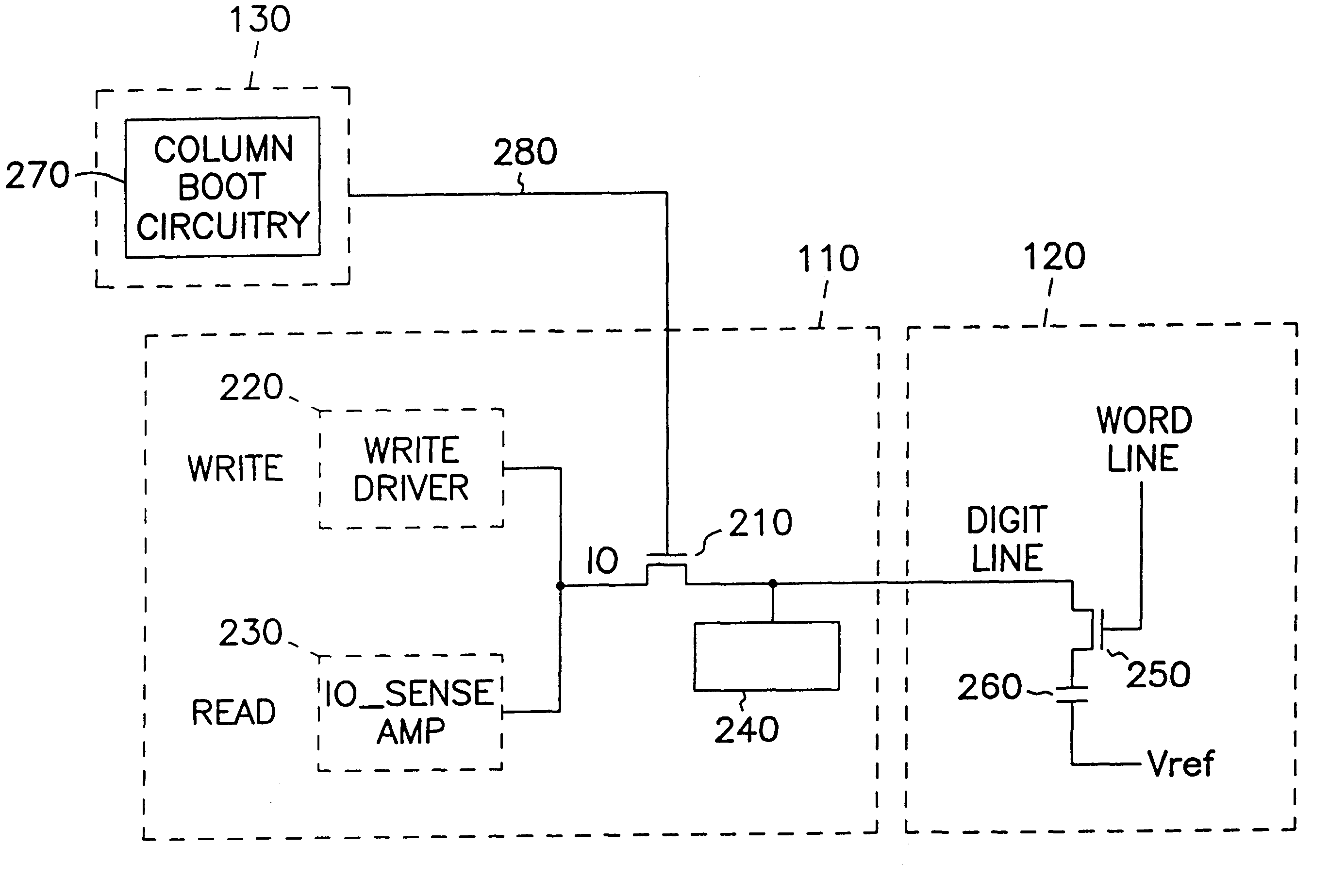
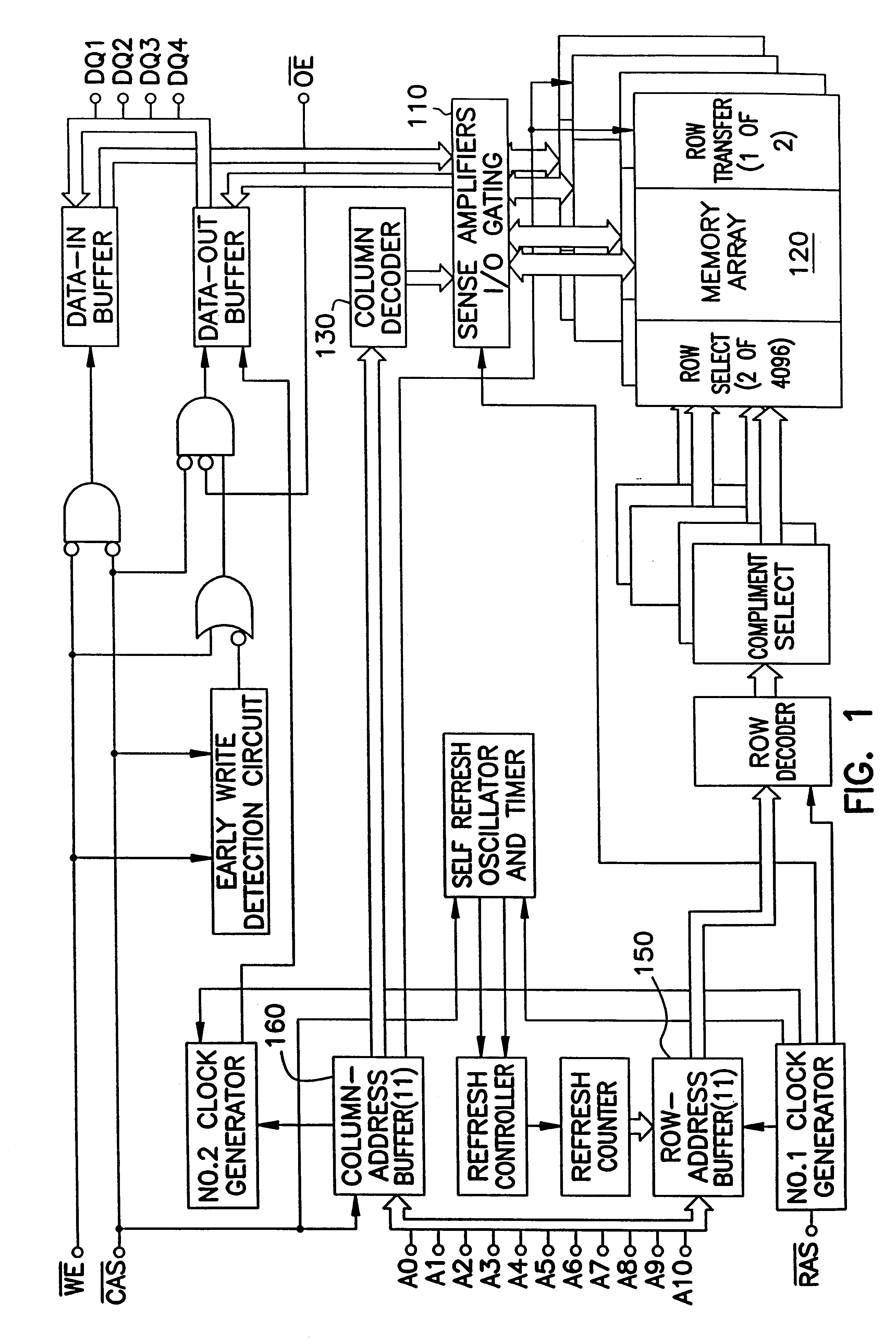
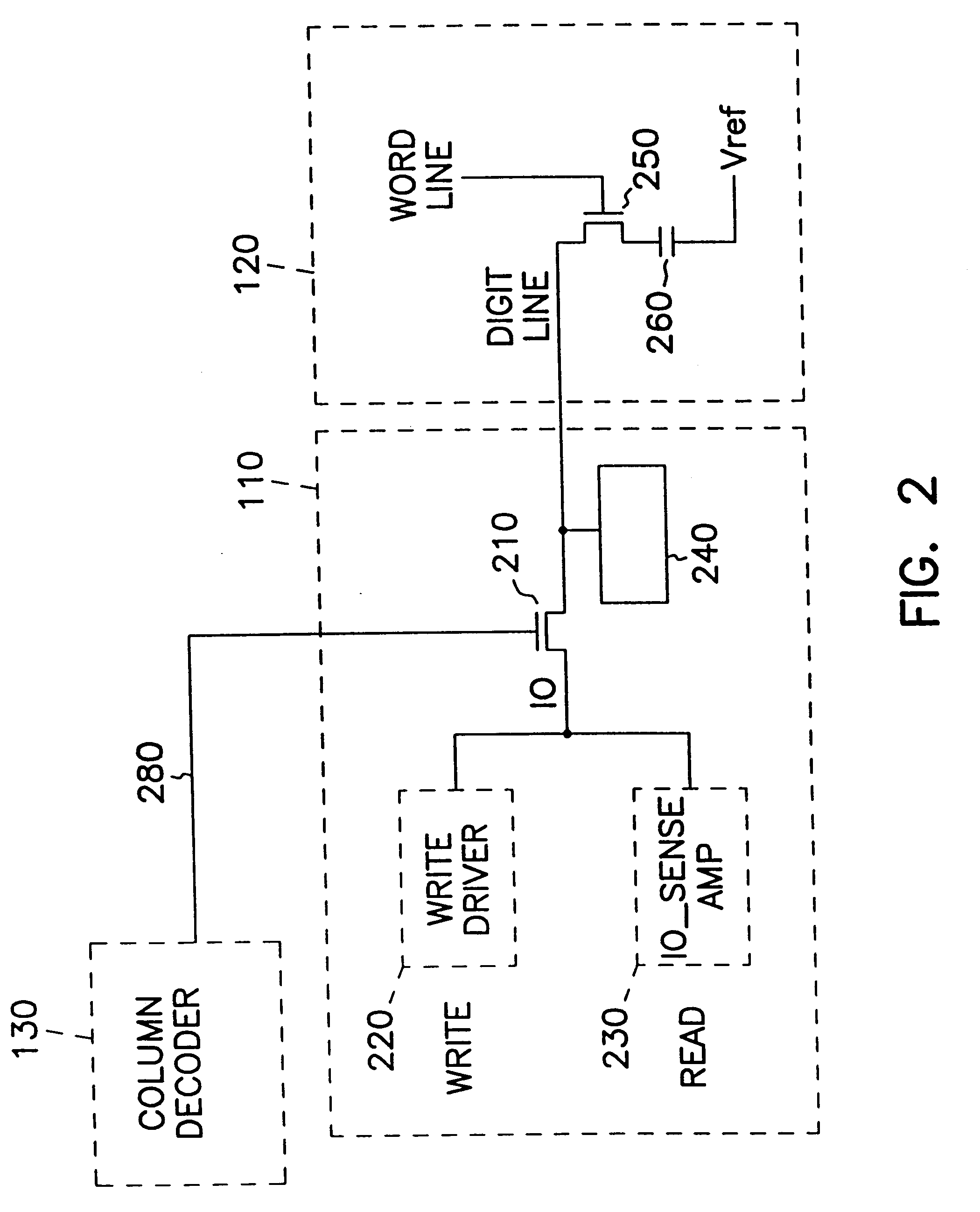
FIG. 1 is a functional block diagram of a Dynamic Random Access Memory (DRAM), which is one environment in which the present memory access system may be practiced. Those skilled in the art will readily recognize that other applications of the present memory access system a...


PUM


Abstract

A voltage booting circuit for booting the switching signal applied to a column access passgate is employed to reduce the voltage drop across the passgate. Reduction of the voltage dropped across the passgate results in faster read and write times and improved noise margin. In one application the booted voltage is used only during a write operation, but not during a read. In another application, the booted voltage is used during both operations.

Description

FIELD OF THE INVENTIONThe present invention relates generally to a system for improved memory cell access, and in particular to a booted column access system for rapid memory cell read and write.BACKGROUND OF THE INVENTIONImprovements in memory device applications result in larger cell arrays and faster memory access requirements. For example, dynamic random access memories (DRAMs) use an array of memory cells, sense amplifiers, drivers and support electronics to manage data read, data write and cell refresh operations. The memory cells are generally miniature capacitors which vary in stored charge according to the voltage written to the cell. Since each memory cell has leakage losses, each cell must be refreshed periodically to prevent loss of the information in each cell. This is called a "writeback" operation and is performed by periodically reading each cell and refreshing the cell by internally writing a logic one to the cells storing a one. Additionally, each cell is rewritten...

Claims


Application Information

Patent Timeline
Patent Type & Authority Patents(United States)
IPC IPC(8): G11C7/00G11C7/10G11C11/4096
CPCG11C11/4096G11C7/1048
Inventor ZHENG, HUA
Owner MICRON TECH INC
Why Eureka
Try Eureka