Transmission device, electric field communication transceiver, and electric field communication system
a technology of transmission device and transmission device, which is applied in the direction of electric signalling details, instruments, signalling systems, etc., can solve the problems of inability to obtain sufficient voltage in a down-sized transceiver or transmission device, difficult to carry out communications, and wearable computers that can be worn on a human body. , to achieve the effect of excellent communication and small circuit size, low electricity consumption
- Summary
- Abstract
- Description
- Claims
- Application Information
AI Technical Summary
Benefits of technology
Problems solved by technology
Method used
Image
Examples
first embodiment
A First Embodiment
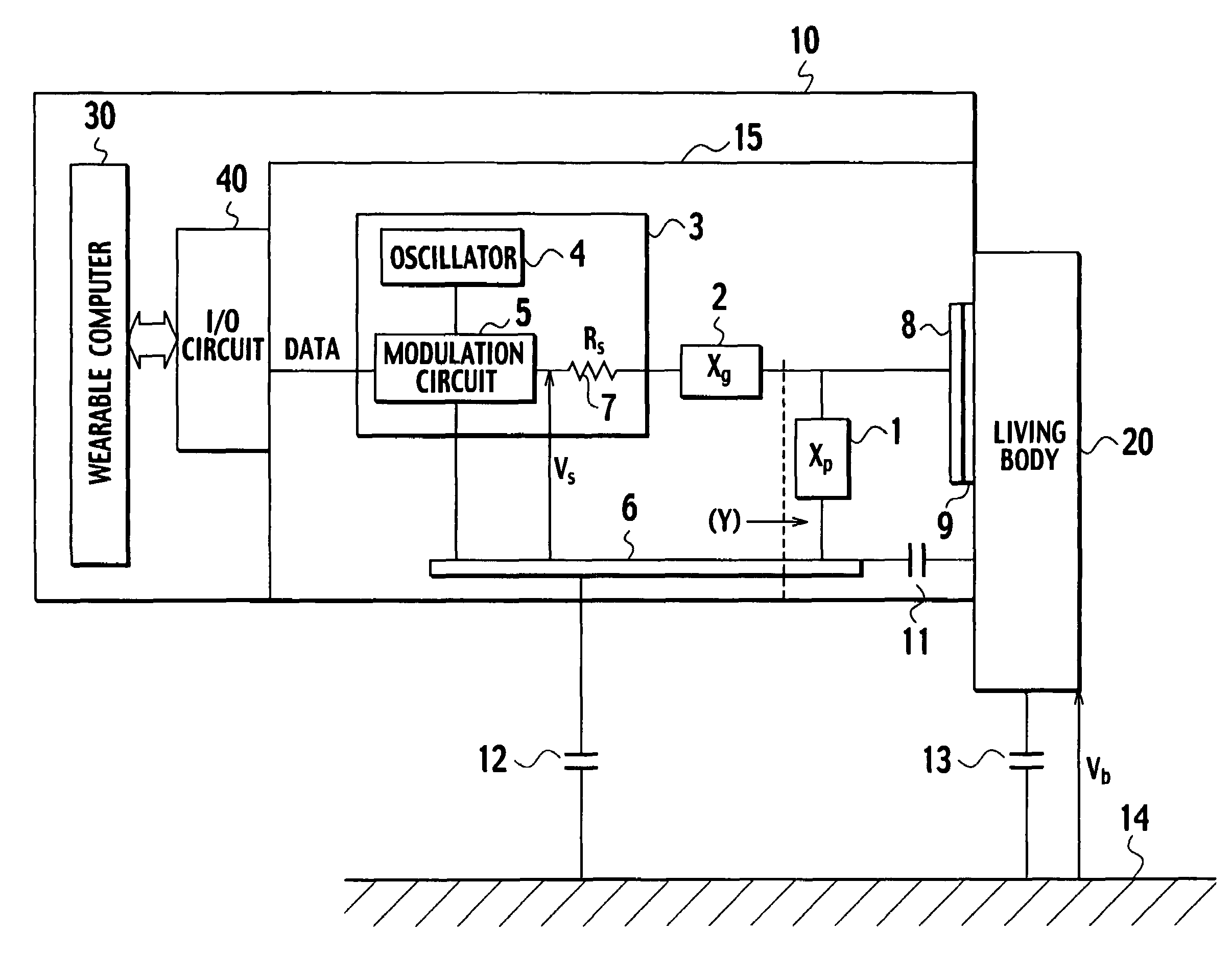
[0125]FIG. 8 illustrates a block diagram of a transceiver 15 according to a first embodiment of the present invention.
[0126]In FIG. 8, the transceiver 15 indicated by a broken line, an I / O circuit 40 connected to the transceiver 15, an insulator 9 that contacts to the living body 20 (not shown, but referable to in FIG. 6), and a transmission / reception electrode 8 disposed beneath the insulator 9.
[0127]In addition, the transceiver 15 is provided with a reception section 23, a transmission section 16, a switch 17, a switch 18, a variable reactance section Xg 19, a variable reactance section Xp 21, and a reactance control section 22. One end of the switch 18 is connected to a circuit ground 29.
[0128]The transceiver 15 having such a configuration supports half-duplex transmission in which the switches 17, 18 turn on at the state of transmission and off at the state of reception. In addition, the transceiver 15 is provided with the variable reactance Xg 19 and a reactan...
second embodiment
A Second Embodiment
[0136]FIG. 11 illustrates a block diagram of a transceiver according to a second embodiment of the present invention. This transceiver adjusts each variable reactance at one time of adjustment, respectively. To this end, a switch 32, a switch 18 and a resistor 33 as a load resistance are provided. First of all, in order to adjust the variable reactance section Xp 21, a1 contacts with b1 in the switch 32; a2 contacts with b2 in the switch 32; and the switch 18 turns on.
[0137]FIG. 12 illustrates a block diagram in order to describe an inner configuration of the reactance control section 22. This configuration as illustrated in FIG. 12 is substantially the same as that already illustrated in FIG. 9 but different in that a condition switching signal is outputted from an adjustment signal generation section 24.
[0138]FIG. 13 illustrates an equivalent circuit according to the second embodiment of the present invention. In this equivalent circuit, there are shown a signal...
third embodiment
A Third Embodiment
[0154]FIG. 16 is a block diagram of a transceiver 15 according to a third embodiment of the present invention.
[0155]In the transceiver 15 shown in FIG. 16, a self-adjusting variable reactance section 52 that is capable of adjusting a reactance value without requiring a control section, instead of the variable reactance section Xp 21 in the first and the second embodiment.
[0156]FIG. 17 illustrates a specific configuration of the self-adjusting variable reactance section 52. Capacitors 53, 55 serve to block a direct current component and are considered as short-circuited for an alternating signal. FIG. 18A illustrates a relation between a direct current component ID and alternating voltage applied therebetween when the alternating voltage having an altitude of |VAC| is applied to a variable capacitance diode 56. When reverse-biased voltage VDC is generated across the variable capacitance diode 56, the variable capacitance diode 56 becomes short-circuited for shorter ...
PUM
 Abstract
Description
Claims
Application Information
 - R&D
- Intellectual Property
- Life Sciences
- Materials
- Tech Scout
- Unparalleled Data Quality
- Higher Quality Content
- 60% Fewer Hallucinations
Browse by: Latest US Patents, China's latest patents, Technical Efficacy Thesaurus, Application Domain, Technology Topic, Popular Technical Reports.
© 2025 PatSnap. All rights reserved.Legal|Privacy policy|Modern Slavery Act Transparency Statement|Sitemap|About US| Contact US: help@patsnap.com


