Quick-release device for a pneumatic nail gun magazine

a technology of pneumatic nail gun and quick-release device, which is applied in the direction of instruments, manufacturing tools, de-stacking articles, etc., can solve the problems of finger easily injured and troublesome operation of conventional quick-release devi

Inactive Publication Date: 2001-09-18
REXON IND CORP LTD
View PDF6 Cites 82 Cited by
  • Summary
  • Abstract
  • Description
  • Claims
  • Application Information

AI Technical Summary

Problems solved by technology

The operation of the conventional quick-release device is very troublesome.
In addition, because the finger

Method used


Image

  • Quick-release device for a pneumatic nail gun magazine
  • Quick-release device for a pneumatic nail gun magazine
  • Quick-release device for a pneumatic nail gun magazine

Examples


Embodiment Construction

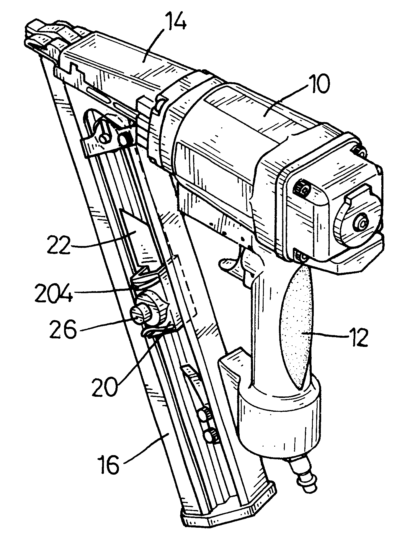
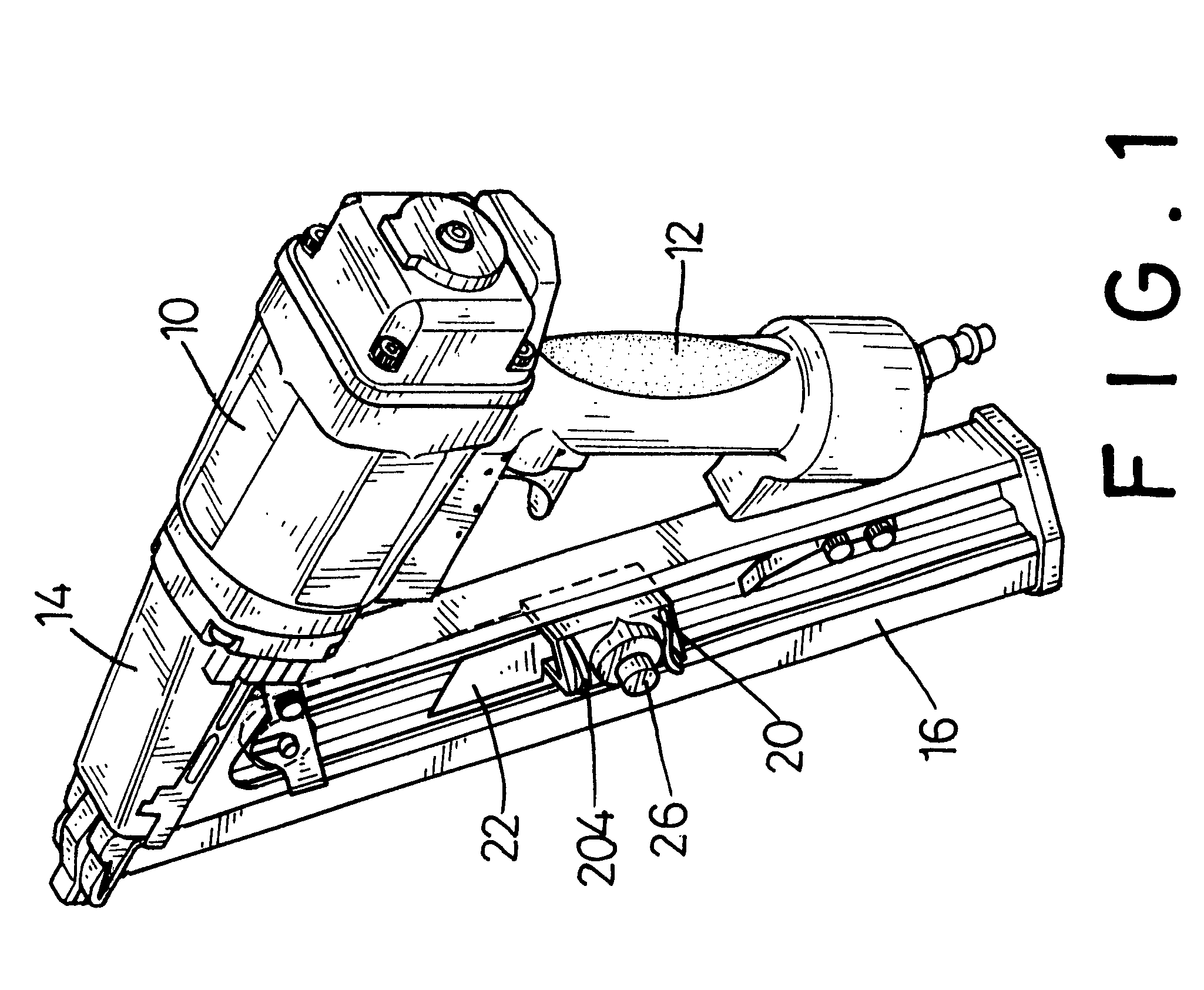
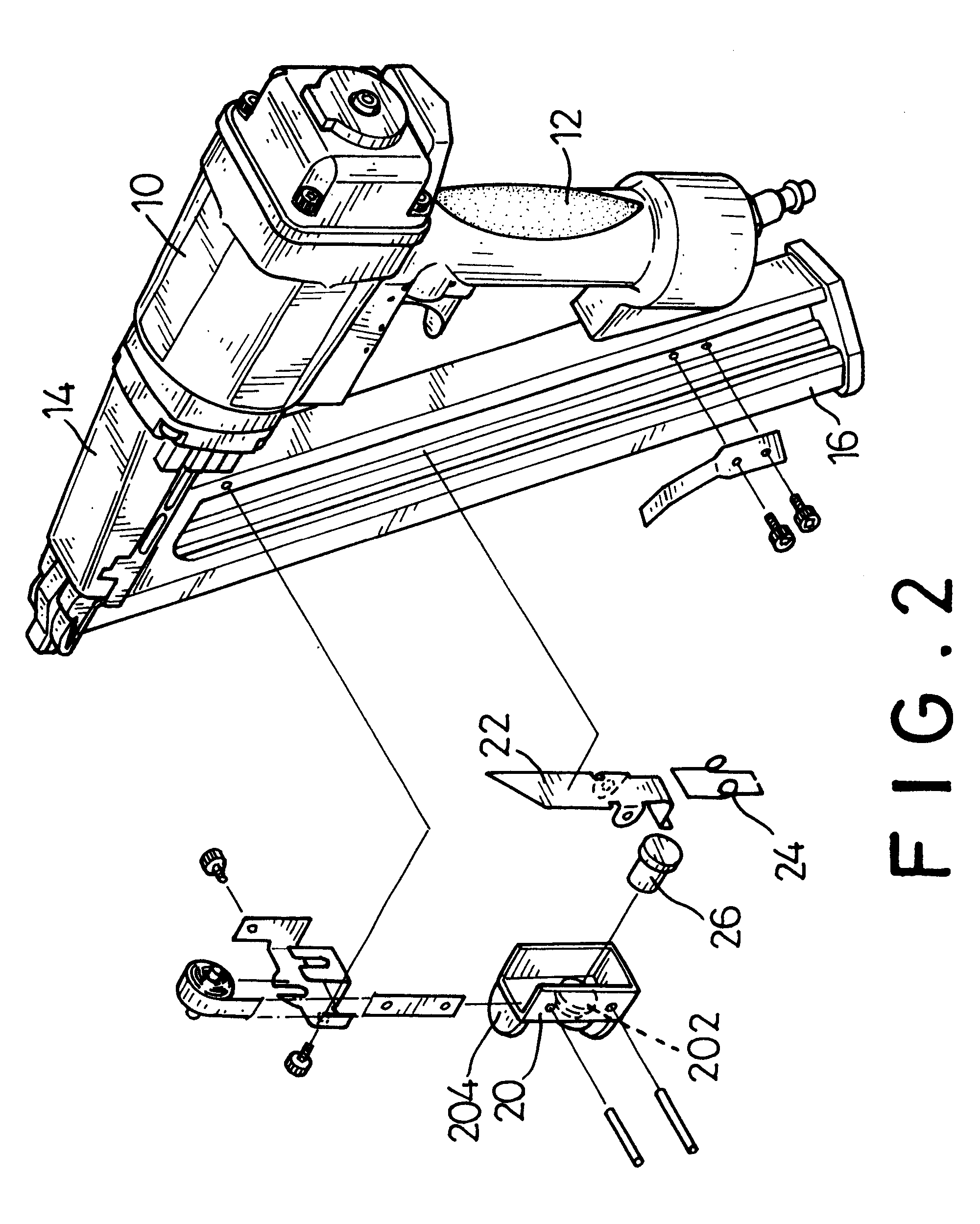
With reference to FIGS. 1 to 3, a quick-release device in accordance with the present invention for a pneumatic nail gun having a body (10), a handle (12), a barrel (14) and a magazine (16) comprises a base (20), a pusher plate (22), a spring (24) and a button (26). The base (20) is adapted to be slidably mounted on the magazine (16) of a pneumatic nail gun. A through hole (202) is defined in the top of the base (20). The pusher plate (22) is pivotally mounted in the base (20). The pusher plate (22) has a first end that normally extends into the channel of the magazine (16) and a second end. The spring (24) abuts the second end of the pusher plate (22), such that the first end of the pusher plate (22) is normally held in the channel to push the nails. The button (26) is moveably mounted in the base (20) and extends out from the through hole (202). The button (26) abuts the second end of the pusher plate (22).

With reference to FIG. 4, when a nail blockage occurs, the user just pushes...


PUM


Abstract

A quick-release device for a pneumatic nail gun with a magazine has a base, a pusher plate, a spring and a button. The base has a through hole defined in the top of the base. The pusher plate has a first end that normally extends into the channel of the magazine and a second end. The spring abuts the second end of the pusher plate. The button is moveably mounted in the base and extends out from the through hole. The button abuts the second end of the pusher plate, such that the pusher plate can be pivoted by pressing the exposed button. The finger of the user does not extend into the device. Consequently, the operation of the quick-release device is simplified, and the finger of the user will not be injured during the process of clearing jammed nails.

Description

1. Field of the InventionThe present invention relates to a quick-release device, and more particularly to a quick-release device for a pneumatic nail gun magazine to gain access to nails jammed in the magazine.2. Description of Related ArtA pneumatic nail gun is used to join two objects by shooting a nail through both objects. With reference to FIG. 5, a conventional pneumatic nail gun comprises a hollow body (30), a handle (32), a barrel (34) and a magazine (36). A compressed air mechanism (not shown) is mounted in the body (30) to propel the nail. The handle (32) integrally extends from one end of the body (30). The barrel (34) is secured to the other end of the body (30). The magazine (36) is connected to the barrel (34). A channel is defined in the magazine (36) to receive the nails and communicate with the barrel (34), such that the nails can be pushed into the barrel (34) through the channel in the magazine (36) one after another.A quick-release device is mounted on the magaz...

Claims


Application Information

Patent Timeline
IPC IPC(8): B25C1/00B25C5/00B25C5/16
CPCB25C5/161B25C1/005
Inventor CHEN, RUEY-ZON
Owner REXON IND CORP LTD
Why Eureka
Try Eureka