Fluid delivery apparatus with reservoir fill assembly

a technology of reservoir filling and delivery apparatus, which is applied in the direction of process and machine control, laboratory glassware, instruments, etc., can solve the problems of insufficient accuracy of inconvenient use, and inability to accurately control the delivery of such drugs. , to achieve the effect of enhancing the activity of drugs and increasing the need for accuracy in controlling the delivery of such drugs

Inactive Publication Date: 2001-09-25
PESCADERO BEACH HLDG
View PDF8 Cites 76 Cited by
  • Summary
  • Abstract
  • Description
  • Claims
  • Application Information

AI Technical Summary

Benefits of technology

Many medicinal agents require an intravenous route for administration thus bypassing the digestive system and precluding degradation by the catalytic enzymes in the digestive tract and the liver. The use of more potent medications at elevated concentrations has also increased the need for accuracy in controlling the delivery of such drugs. The delivery device, while not an active pharmacologic agent, may enhance the activity of the drug by mediating its therapeutic effectiveness. Certain classes of new pharmacologic agents possess a very narrow range of therapeutic effectiveness, for instance, too small a dose results in no effect, while too great a dose results in toxic reaction.
Another object of the invention is to provide a novel reservoir fill assembly for use with the fluid dispenser subassembly of the apparatus which is easy to use, is inexpensive to manufacture, and one which maintains the container in a substantially aseptic condition until time of use.

Problems solved by technology

Certain classes of new pharmacologic agents possess a very narrow range of therapeutic effectiveness, for instance, too small a dose results in no effect, while too great a dose results in toxic reaction.
Such methods are cumbersome, imprecise and require bed confinement of the patient.
The prior art bladder type infusion devices are not without drawbacks.
Generally, because of the very nature of bladder or "balloon" configuration, the devices are unwieldy and are difficult and expensive to manufacture and use.
Further, the devices are somewhat unreliable and their fluid discharge rates are frequently imprecise.

Method used


Image

  • Fluid delivery apparatus with reservoir fill assembly
  • Fluid delivery apparatus with reservoir fill assembly
  • Fluid delivery apparatus with reservoir fill assembly

Examples


Embodiment Construction

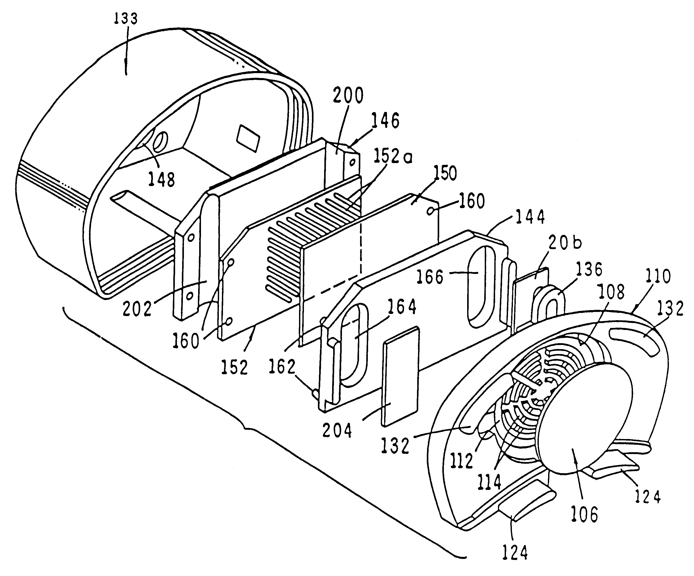
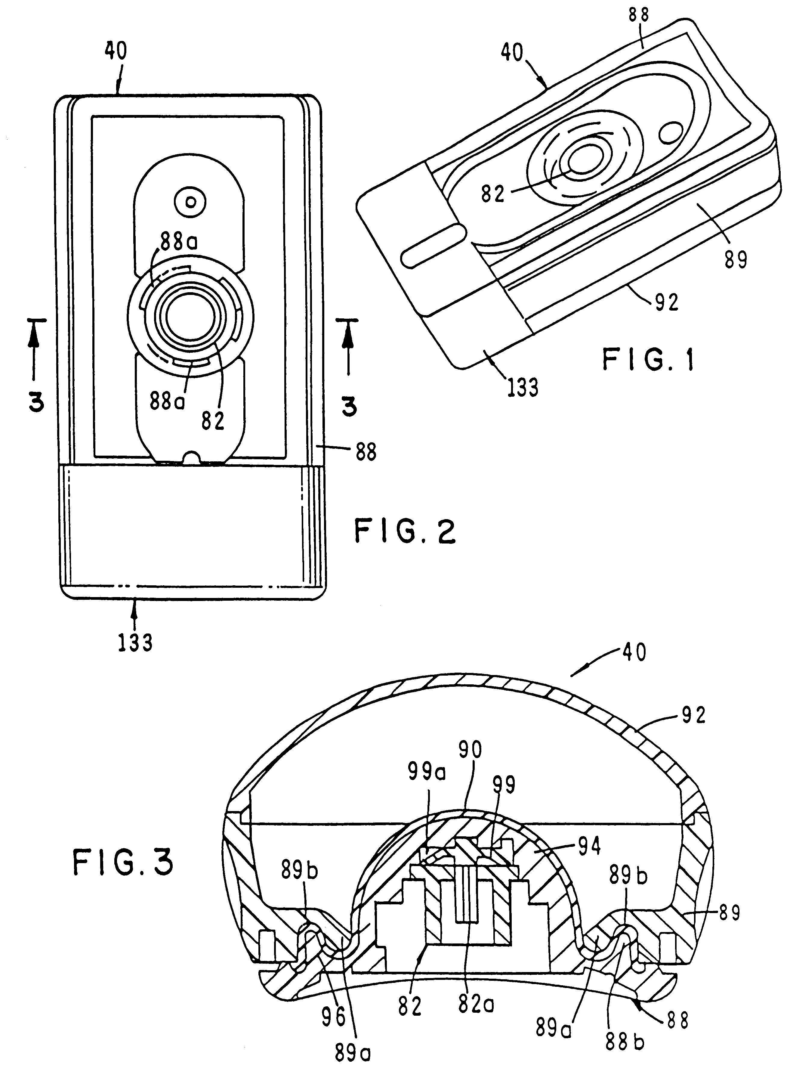
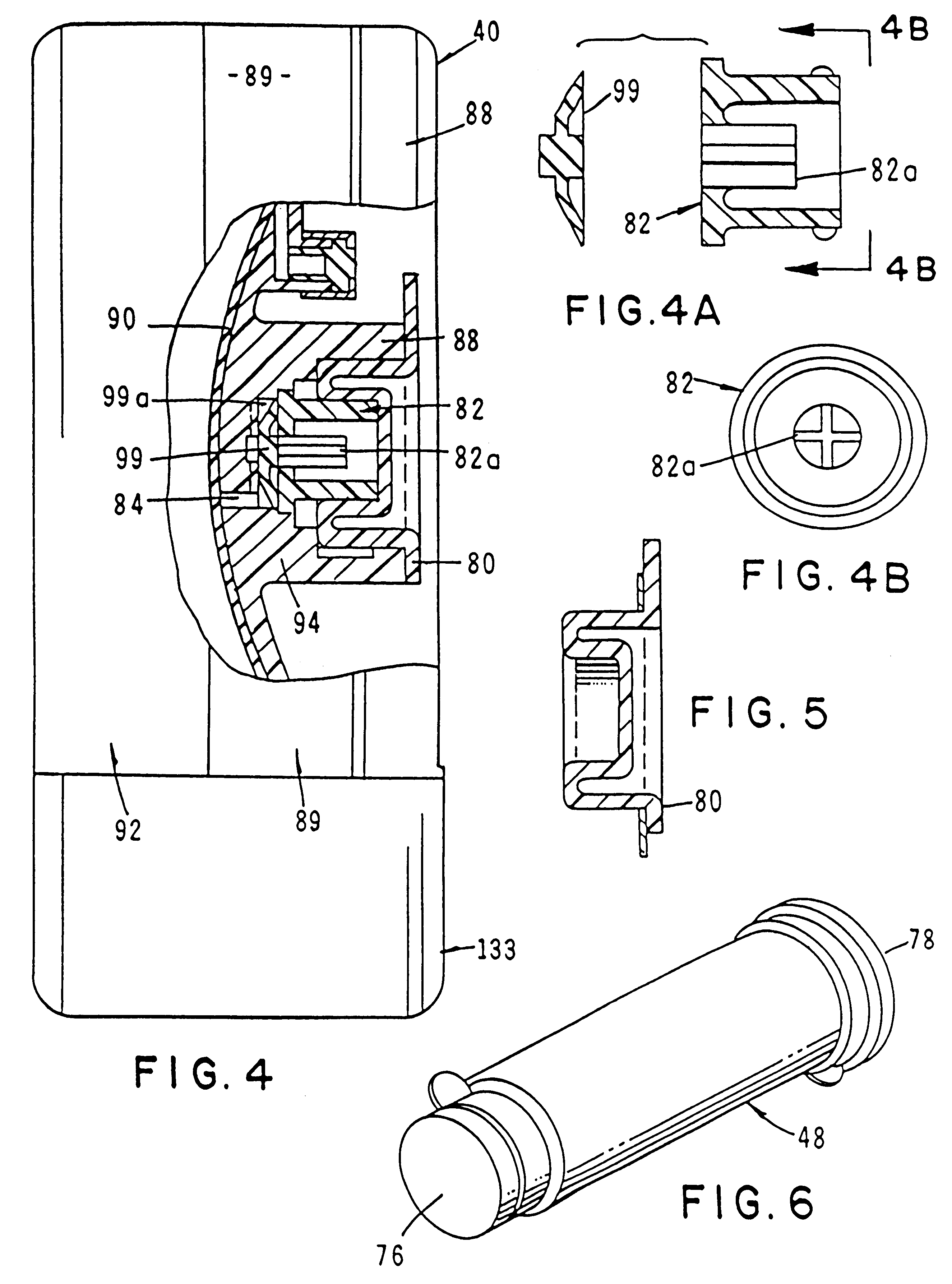
Referring to the drawings and particularly to FIGS. 1 through 7, one form of the apparatus of this latest form of the present invention is there illustrated. As best seen in FIG. 7, the apparatus here comprises two major cooperating assemblies, namely a fluid dispensing apparatus or fluid dispenser 40 and a reservoir fill assembly 42 which can be operably coupled with fluid dispenser 40. As will be described in greater detail hereinafter, dispenser 40 is made up of three major cooperating subassemblies namely, a reservoir subassembly, a flow rate control subassembly, and a flow indicator subassembly.

Turning particularly to FIGS. 9 through 16, the novel reservoir fill assembly 42 of the invention can be seen to also comprise three major components, namely a container subassembly 46 (FIG. 16), an adapter subassembly 48 (FIG. 9) and an adapter or pusher sleeve 50 (FIG. 16). Container subassembly 46 includes a container such as a vial 52 which contains the medicinal fluid with which the...


PUM


Abstract

An apparatus for delivering fluids at a precisely controlled rate which includes a fluid dispensing component having a fluid reservoir for containing the fluids to be delivered and a reservoir fill component which can be removably interconnected with the fluid dispensing component. The reservoir fill assembly is uniquely designed to accept a vial component of conventional construction which is factory filled with the medicinal fluid to be delivered to the patient. The dispenser component embodies a highly novel fluid flow indicator that provides a readily discernible visual indication of fluid flow status through the device.

Description

Field of the InventionThe present invention relates generally to fluid delivery devices. More particularly, the invention concerns an improved apparatus, including a fluid dispenser having visual flow indicator means, for infusing medicinal agents into an ambulatory patient at specific rates over extended periods of time and a novel reservoir fill assembly for controllably filling the reservoir of the fluid dispenser.DISCUSSION OF THE INVENTIONMany medicinal agents require an intravenous route for administration thus bypassing the digestive system and precluding degradation by the catalytic enzymes in the digestive tract and the liver. The use of more potent medications at elevated concentrations has also increased the need for accuracy in controlling the delivery of such drugs. The delivery device, while not an active pharmacologic agent, may enhance the activity of the drug by mediating its therapeutic effectiveness. Certain classes of new pharmacologic agents possess a very narro...

Claims


Application Information

Patent Timeline
Patent Type & Authority Patents(United States)
IPC IPC(8): A61M5/168A61M5/145A61M5/152G01P13/00A61M37/00
CPCG01P13/0026G01P13/0066G01P1/07A61M5/16854A61M5/16886A61M5/152A61M2209/045A61M2205/583
Inventor KRIESEL, MARSHALL S.ARNOLD, STEVEN M.GARRISON, JAMESKAZEMZADEH, FARHAD
Owner PESCADERO BEACH HLDG
Why Eureka
Try Eureka