
Telescopic pocket door angle drill

Inactive Publication Date: 2001-09-25
SMITH JAMES C
View PDF13 Cites 43 Cited by
  • Summary
  • Abstract
  • Description
  • Claims
  • Application Information

AI Technical Summary

Benefits of technology

The present invention overcomes the limitations of the related art and provides a general solution to the problem of installing and removing pocket door hardware. Most importantly, the present invention provides a pocket door angle drill having a telescopically extendable handle so that pocket door track screws can easily be installed and removed.
Running substantially the entire length of the exterior shell is a solid rotatable primary drive shaft which is slidably inserted into a tightly fitting hollow hexagonal tube. At its proximal end, the primary drive shaft is connected to the angle drill's horizontal drive shaft by a hexagonal socket that rotates freely within the exterior shell. This coupling provides stability for the primary drive shaft at the proximal end of the primary drive shaft housing. At its proximal end, the hollow hexagonal tube is stabilized by a bushing or set of bearings secured within the internal sleeve member. At its distal end it terminates at a second hexagonal socket, which also connects the hexagonal tube to a short segment of solid hexagonal drive shaft constituting a secondary drive shaft. The hexagonal socket is bracketed within the internal sleeve member by two bushings or bearing sets.

Problems solved by technology

Use of the door after it is off the track can result in damage to the track and to the rollers mounted on the door.
This tool, while suitable for applying rotary power at right angles to the workpiece or fastening devices, is not suitable for work in confined spaces.
This tool provides considerable flexibility in positioning the tool handle relative to the tool head, but it is ill-suited for work in deeply confined spaces requiring an extended handle portion.
Again, while this device provides a convenient means to connect a detachable handle at 90 degrees relative to a drill or screwdriver, it does not include any means to extend the handle for reaching into distant spaces.
While the device disclosed in the '542 patent has many of the desired features for work in pocket door openings, its extendable operating component is not truly telescopic and has a single, fixed operating position when extended.
To date there is as yet no known device that provides truly telescopic extension the drive shaft of an angle drill suitable for use in removing and installing pocket door hardware.

Method used


Image

  • Telescopic pocket door angle drill
  • Telescopic pocket door angle drill
  • Telescopic pocket door angle drill

Examples


Embodiment Construction

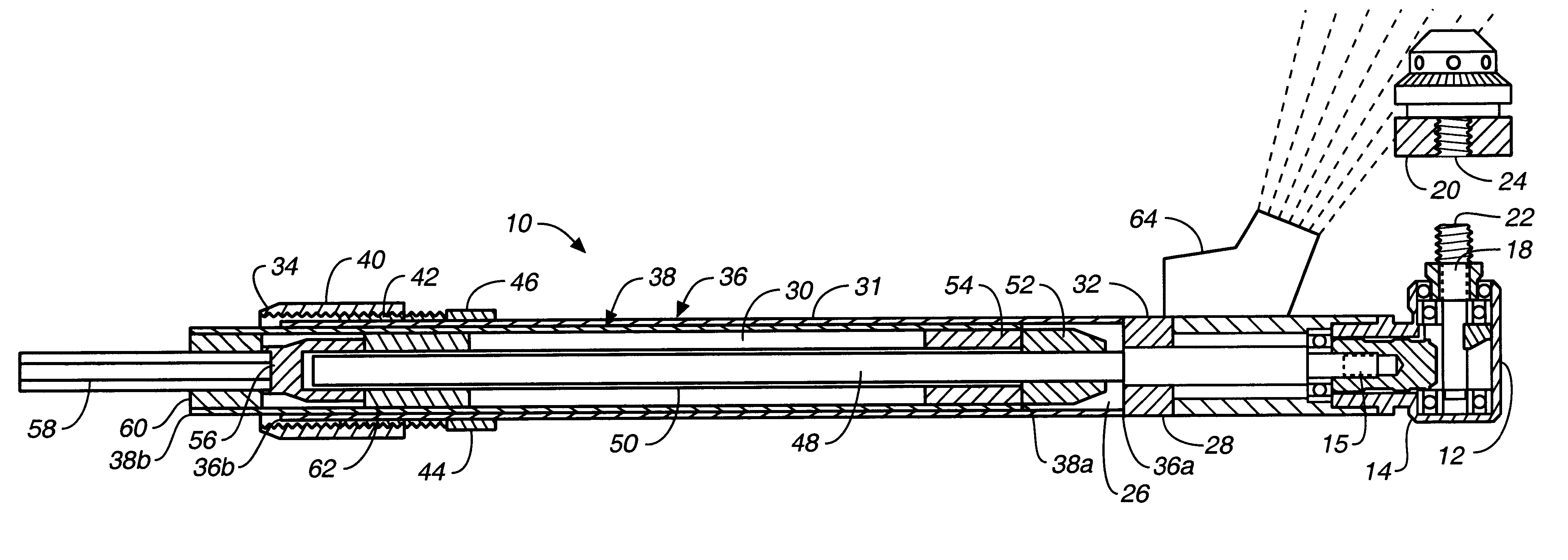
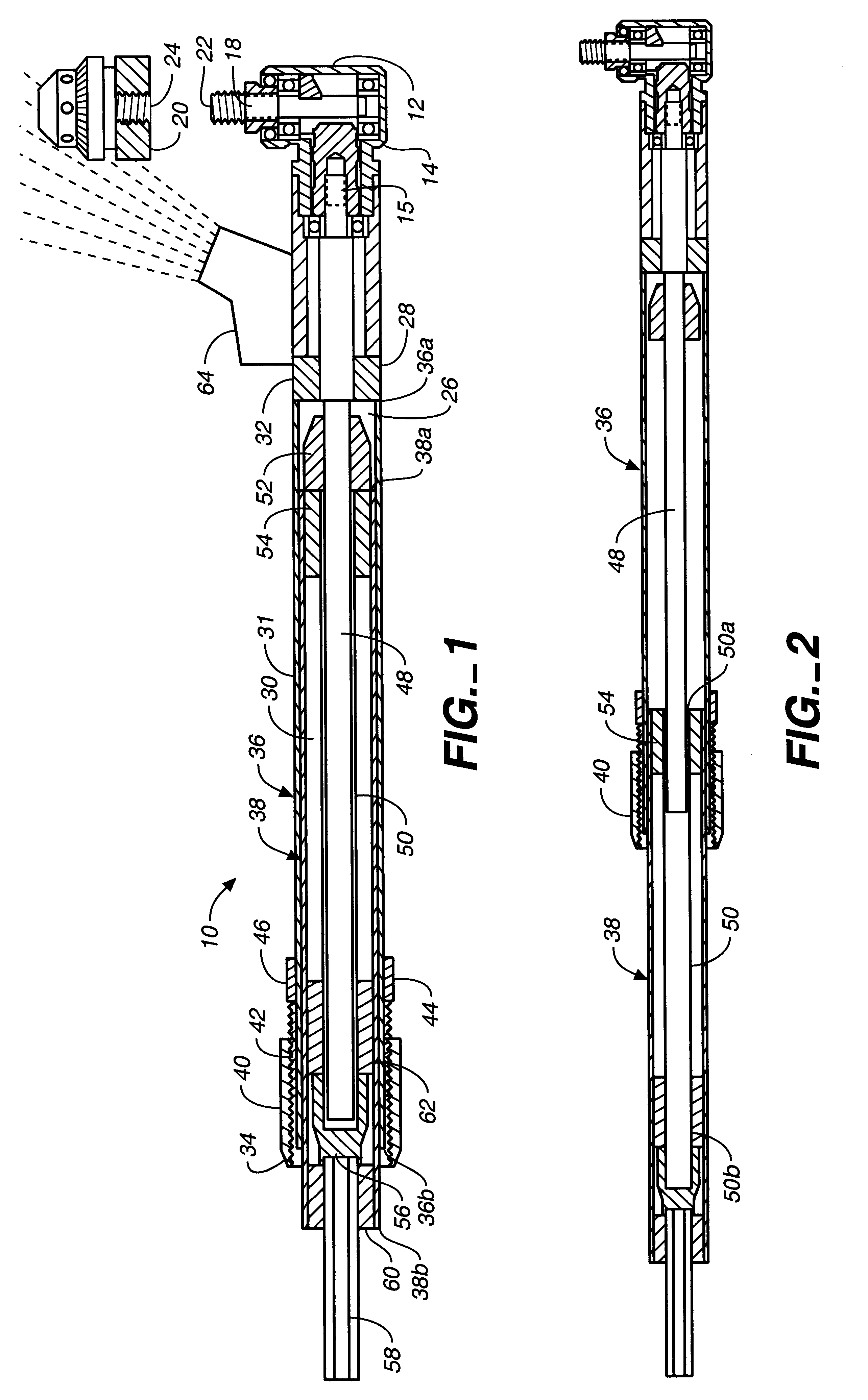
FIG. 1 is a cross-sectional side elevation view of the first preferred embodiment of the telescopic pocket door angle drill 10 of the present invention, showing the device in the nonextended, or closed configuration, and FIG. 2 is a cross-sectional side elevation view of the apparatus of FIG. 1, showing the device in an extended configuration. These views show that in the most general terms the inventive apparatus 10 comprises a conventional right angle driver having a telescopic handle portion that may be extended to reach into confined spaces. More particularly, the telescopic right angle drill comprises a driver 12 suitable for driving and removing screws, said driver having a drive casing 14 and an internal gear assembly for translating rotary motion from a first horizontal drive shaft 16 operating in a first plane to a second vertical drive shaft 18 operating in a second plane substantially 90 degrees relative to said first plane, as is well known in the art. The vertical drive...


PUM


Abstract

A pocket door angle drill having a right angle driver with a truly telescopic handle portion that may be extended to reach into confined spaces. The right angle driver has a casing and an internal gear assembly for translating rotary motion from a horizontal drive shaft to a vertical drive shaft. The drill further includes a telescopically extendable primary drive shaft portion that may be operatively connected to a power rotary device, and, optionally, an extension pole having an extension drive shaft for providing access to remote confined spaces.

Description

1. Cross Reference to Related ApplicationsNot applicable.2. Field of the InventionThe present invention relates generally to hand tools for working in confined spaces, and more particularly to a telescopically extendable angle drill adapted for use in removing and installing pocket door track hardware.3. Discussion of Related ArtPocket doors are notorious for jumping off their roller tracks. Use of the door after it is off the track can result in damage to the track and to the rollers mounted on the door. When this happens, it is typically necessary to remove the door from its pocket by tearing out a substantial portion of the wall defining the door pocket. Because of the inconvenience and expense of such a repair, it would be desirable to have a power tool capable of removing the fastening screws in damaged pocket door hardware and installing fastening screws for replacement hardware without the need to do any structural tear out. More specifically, it would be desirable to provide...

Claims


Application Information

Patent Timeline
IPC IPC(8): B23Q17/24B25B13/00B23Q5/00B23Q5/04B25B23/18B25B13/48B25B23/00B25B21/00
CPCB23Q5/043B23Q5/045B25B23/18B25B13/481B25B21/002B23Q17/24
Inventor SMITH, JAMES C.
Owner SMITH JAMES C
Learn More