Antenna apparatus and portable radio communication apparatus
a portable radio communication and antenna device technology, applied in the direction of resonant antennas, polarised antenna unit combinations, differential interacting antenna combinations, etc., can solve the problems of complex housing structure at the time of the apparatus being carried, poor visual appearance of the apparatus from a practical standpoint, and the effect of polarization diversity is hardly expected
- Summary
- Abstract
- Description
- Claims
- Application Information
AI Technical Summary
Benefits of technology
Problems solved by technology
Method used
Image

Examples
first embodiment
(1) First Embodiment
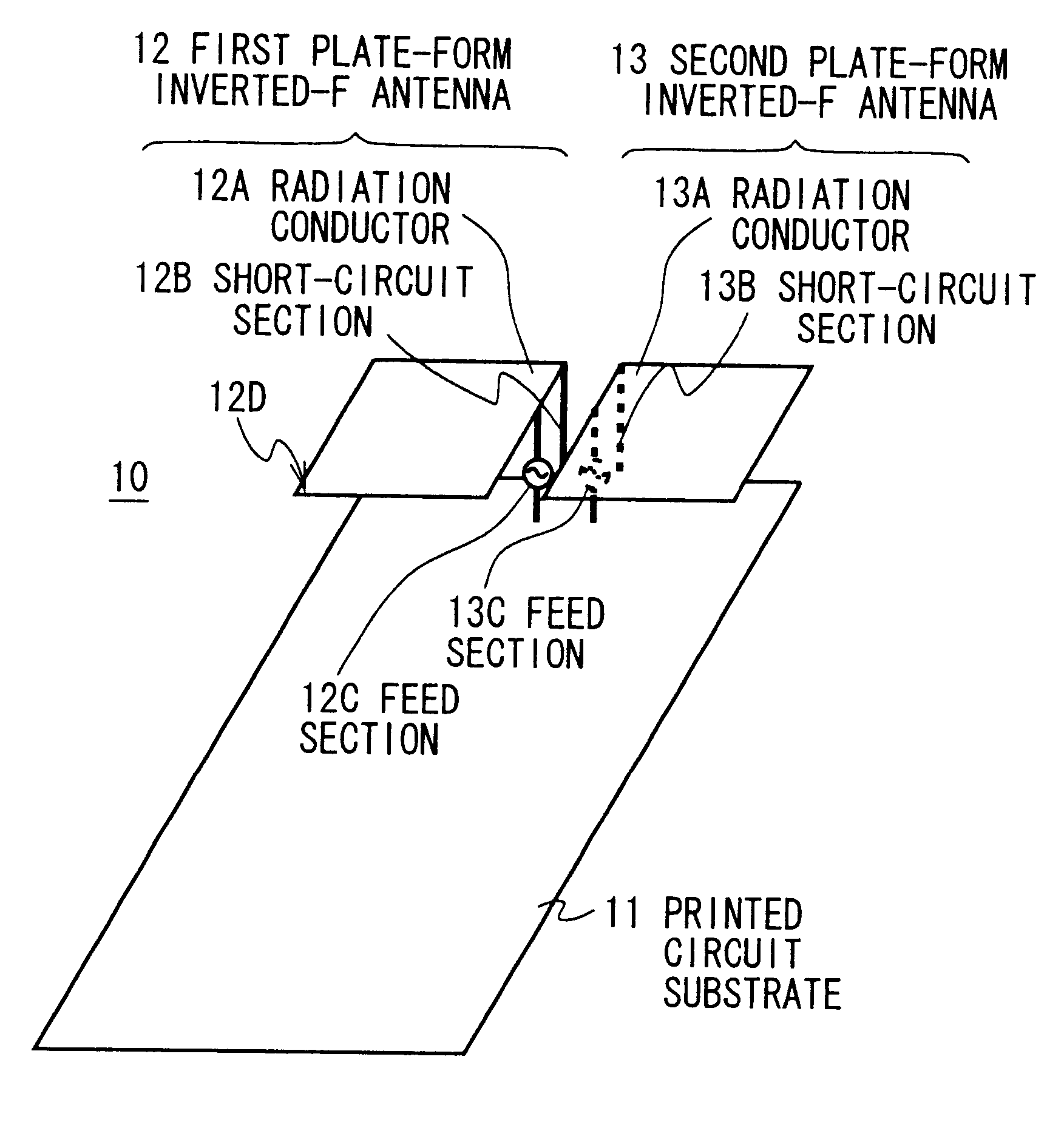
In FIG. 6, reference numeral 10 denotes an antenna apparatus of a first embodiment in its entirety in the present invention, which is configured by comprising a printed circuit substrate 11 as a ground conductor on which various circuits to implement transmission and reception as a portable radio communication apparatus are mounted, a first plate-form inverted-F antenna 12 as well as a second plate-form inverted-F antenna 13 disposed almost in parallel with the above described printed circuit substrate 11.
The first plate-form inverted-F antenna 12 is arranged to have a radiation conductor 12A being rectangular of approximately 1 / 2-wavelength electrical length to be set for its circumference length so as to implement resonance, and is arranged to cause the above described radiation conductor 12A and a printed circuit substrate 11 to short-circuit with a short-circuit section 12B brought into connection with an upward right end of the radiation conductor 12A, and t...
second embodiment
(2) Second Embodiment
In FIG. 13 where the same reference numeral denotes its corresponding portion in FIG. 6, reference numeral 20 denotes an antenna apparatus of a second embodiment in its entirety in the present invention, which is configured, as in the aforementioned antenna apparatus 10 (FIG. 6), by comprising a first plate-form inverted-F antenna 12 as well as a second plate-form inverted-F antenna 13 disposed approximately parallel with a printed circuit substrate 11.
Here, in the aforementioned antenna apparatus 10 (FIG. 6), since the first plate-form inverted-F antenna 12 and the second plate-form inverted-F antenna 13 have approximately the same electrical characteristics and are supplied with power with mutually opposite phase, currents that flow into short-circuit sections 12B and 13B are approximately equal with mutually opposite phase and the potential difference with respect to the ground potential of printed circuit substrate 11 will become 0. Accordingly, in the anten...
third embodiment
(3) Third Embodiment
In FIG. 14 where the same reference numeral denotes its corresponding portion in FIG. 6, reference numeral 30 denotes an antenna apparatus of a third embodiment in its entirety in the present invention, which is configured, as in the aforementioned antenna apparatus 10 (FIG. 6), by comprising a printed circuit substrate 11 and a first plate-form inverted-F antenna 31 as well as a second plate-form inverted-F antenna 32 disposed approximately in parallel with the above described printed circuit substrate 11.
Furthermore, in the antenna apparatus 30, radiation conductors 31A and 32A respectively of the first plate-form inverted-F antenna 31 and the second plate-form inverted-F antenna 32 are provided with slits 31B and 32B resembling rectangular cutout.
At this time, the antenna apparatus 30 is provided with the slits 31B and 32B, enabling current flowing in the radiation conductors 31A and 32A to detour so as to be equivalent to reactance component loaded onto the r...
PUM
 Abstract
Description
Claims
Application Information
 - R&D
- Intellectual Property
- Life Sciences
- Materials
- Tech Scout
- Unparalleled Data Quality
- Higher Quality Content
- 60% Fewer Hallucinations
Browse by: Latest US Patents, China's latest patents, Technical Efficacy Thesaurus, Application Domain, Technology Topic, Popular Technical Reports.
© 2025 PatSnap. All rights reserved.Legal|Privacy policy|Modern Slavery Act Transparency Statement|Sitemap|About US| Contact US: help@patsnap.com