Surface-tracking measuring machine

a technology of surface tracking and measuring machine, which is applied in the direction of mechanical measurement arrangement, mechanical roughness/irregularity measurement, instruments, etc., can solve the problems of limited magnitude of biasing device, increased fluctuation of measuring force, and deterioration of responsivity

Inactive Publication Date: 2001-10-02
MITUTOYO CORP
View PDF9 Cites 72 Cited by
  • Summary
  • Abstract
  • Description
  • Claims
  • Application Information

AI Technical Summary

Problems solved by technology

However, in order to lower the measuring force in accordance with the above first condition, the magnitude of the biasing device is limited.
According to a conventional arrangement, when the measurement range is to be solely widened, some kind of deterioration in performance such as deterioration of the resolution of the displacement sensor, deterioration of responsivity on account of increase of movable portion weight, and increased fluctuation of measuring force is inevitable, which results in difficulty in enlarging the measurement range.
Accordingly, the conventional tracer-type surface roughness measuring machine can not also be used as a profile measuring machine for measuring the profile of the workpiece.

Method used


Image

  • Surface-tracking measuring machine
  • Surface-tracking measuring machine
  • Surface-tracking measuring machine

Examples


Embodiment Construction

)

An embodiment of the present invention will be described below with reference to the drawings.

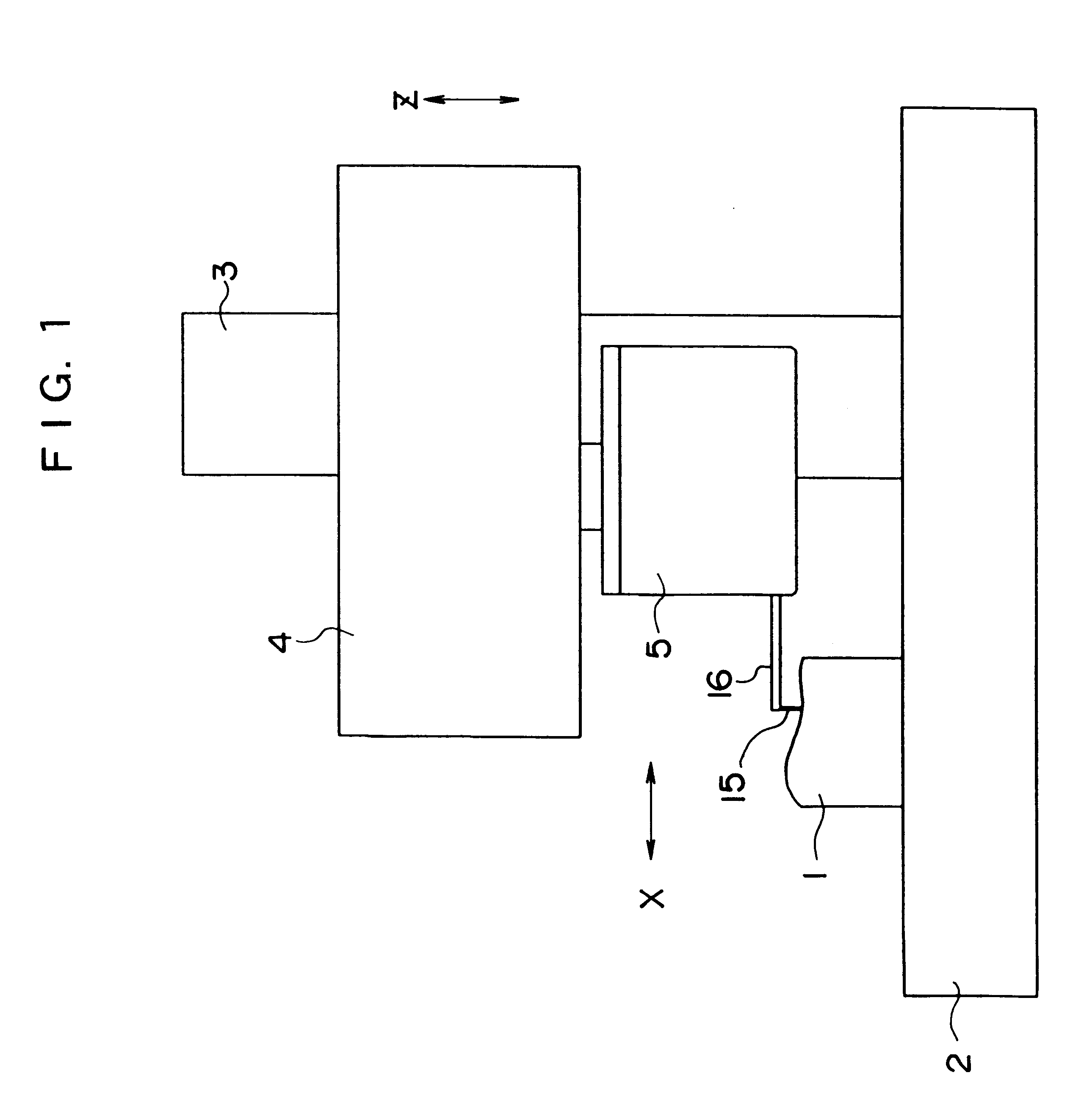
FIG. 1 shows a surface-tracking measuring machine according to the present embodiment. The surface-tracking measuring machine has a table 2 for disposing the workpiece 1 thereon, a column 3 provided on the table 2, a sensing device feeder 4 elevatable in the vertical direction (Z direction) along the column 3, and a sensing device 5 connected under the sensing device feeder 4 and moved in a direction (X direction) orthogonal with the column 3 by the sensing device feeder 4.

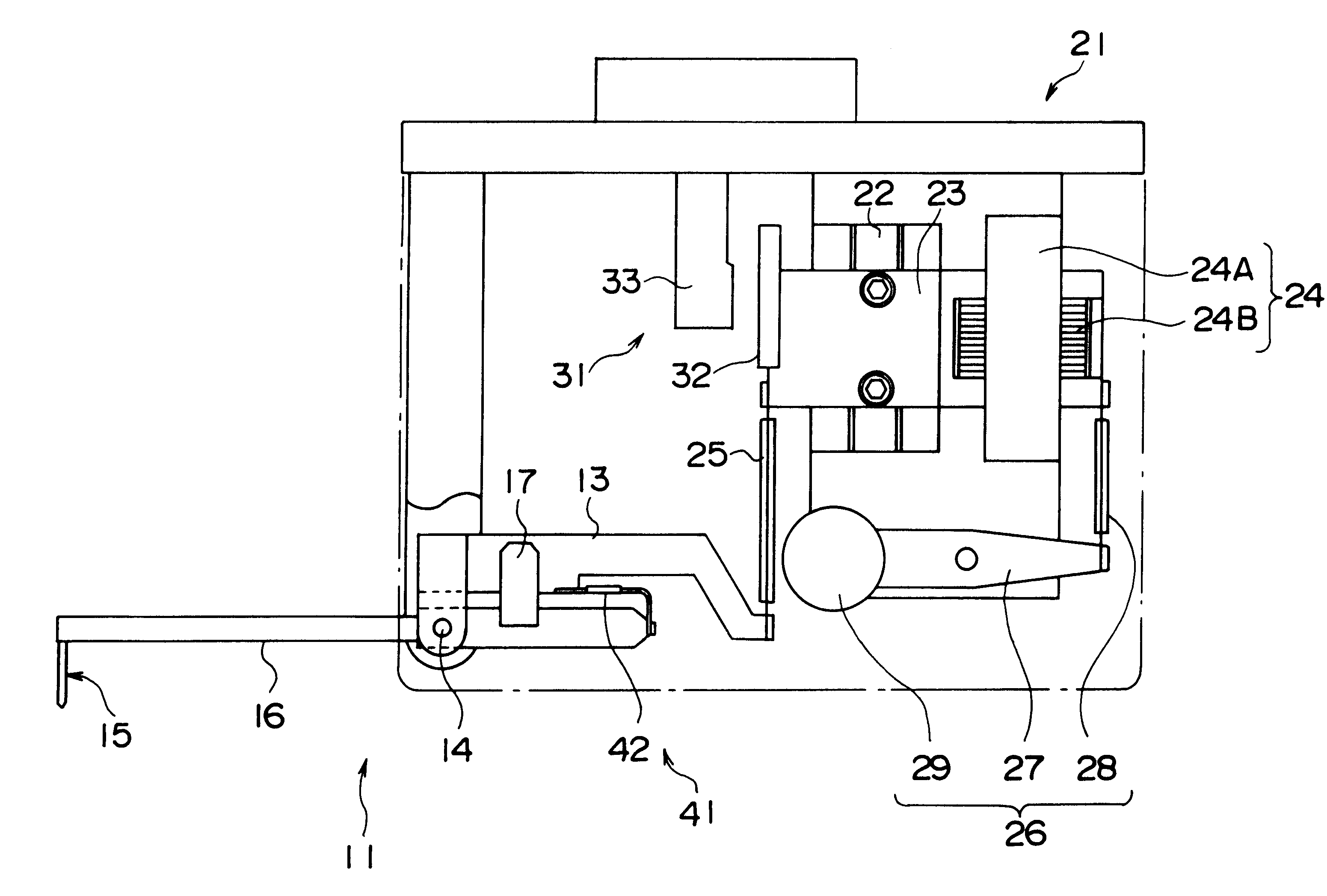
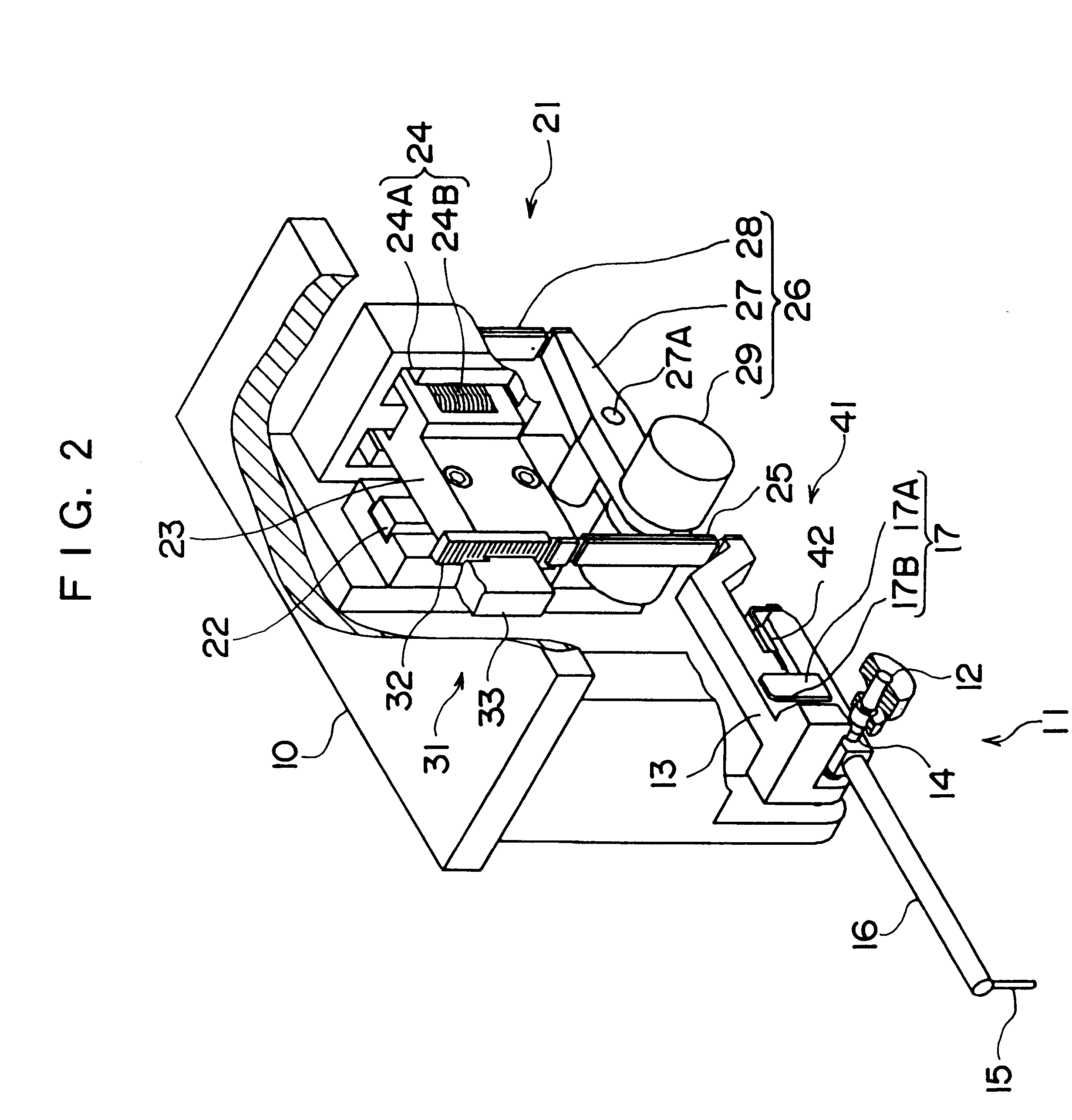
As shown in FIGS. 2, 3 and 4, the sensing device 5 has a frame 10 as a main body connected to the sensing device feeder 4. The frame 10 has a probe 11 having a tracer 15 at an end thereof, a measuring force controller 21 for controlling the measuring force applied to the probe 11, a displacement detector 31 for detecting the displacement of the probe 11, and a measuring force detector 41 for detecting the measuring force...


PUM


Abstract

A surface-tracking measuring machine is provided, in which measurement range is enlarged while keeping a measuring force, responsivity, resolution thereof. For the object, the surface-tracking measuring machine has a frame (10), a probe (11) swingably supported by the frame (10) and having a tracer (15) at an end thereof, a measuring force controller (21) for controlling the measuring force applied to the probe, a displacement detector (31) for detecting a displacement of the probe, a measuring force detector (41) for detecting the measuring force applied to the probe, and a controller (51) for comparing a measuring force detected value detected by the measuring force detector and a previously commanded measuring force command value and to control the measuring force controller so that the measuring force detected value is equal to the measuring force command value.

Description

1. Field of the InventionThe present invention relates to a surface-tracking measuring machine. More specifically, the present invention relates to a surface-tracking measuring machine for measuring a surface roughness and a profile of a workpiece by relatively moving both a tracer and the workpiece while abutting the tracer onto a surface of the workpiece.2. Description of Related ArtA tracer-type surface roughness measuring machine is known as a measuring machine for measuring a surface roughness of the workpiece.The tracer-type surface roughness measuring machine includes a main body, a probe swingably supported by the main body and having a tracer at an end thereof, a biasing device for biasing the tracer of the probe to touch the surface of the workpiece, a moving device for moving the probe in a direction approximately orthogonal with the tracer, and a displacement sensor for detecting a swing displacement amount of the probe.In measuring the surface roughness of the workpiece...

Claims


Application Information

Patent Timeline
Patent Type & Authority Patents(United States)
IPC IPC(8): G01B3/00G01B7/28G01B7/34G01B7/012G01B21/00G01B21/20G01B21/30
CPCG01B3/008G01B7/28G01B7/34
Inventor YAMAMOTO, TAKESHIAKAIKE, TAKENORI
Owner MITUTOYO CORP
Why Eureka
Try Eureka