
Endoscope with at least one reversal system with a non-homogeneous refraction index

a refraction index and reversal system technology, applied in the field of endoscopes with at least one reversal system with a non-homogeneous refraction index, can solve the problem of too high production cost for commercial applications in engineering or medicin

Inactive Publication Date: 2001-10-09
KARL STORZ GMBH & CO KG
View PDF6 Cites 13 Cited by
  • Summary
  • Abstract
  • Description
  • Claims
  • Application Information

AI Technical Summary

Benefits of technology

The advantages of the known reversing systems are avoided in accordance with the invention by the provision that a GRIN rod is used instead of a rod lens with a conventional design, which rod displays a positive dispersion and hence an over-corrected longitudinal chromatic aberration. Due to the inhomogeneity of the refractive index it is now possible to achieve the desired optical effect with planar faces and to compensate yet the astigmatism and the field curvature practically completely. The thin plano-convex lens, which presents an under-corrected longitudinal chromatic aberration, serves substantially to correct the longitudinal chromatic aberration of the GRIN rod.
With the inventive configuration of the reversing or relay lens systems it is hence possible to correct not only the chromatic aberrations of transmission systems in endoscopes but to keep also the field curvature or camber of each reversing system so small that different lenses are not required even with a strongly differing number of reversing systems and thus over a wide range of varying endoscope lengths: in practical operation the same lens may be used with 1 to 15 reversing or relay lens systems, on account of the inventive configuration of the reversing systems for endoscopes, without any occurrence of unacceptable aberrations and particularly field curvatures.
In accordance with Claim 2 the planar surface of the respective thin lens faces the rod lens of the same element. This simplifies the design of the individual reversing systems considerably, particularly when the rod lens and the lens (es) of each element are cemented to each other. But even when the lenses are not cemented the assembly is simplified by spacers which are of a simpler design--due to the opposing planar surfaces.
The inventive structure presents the further advantage that it is not necessary that the thin lens(es) consist(s) equally of a material having an inhomogeneous refractive index. Hence, in accordance with Claim 4, the thin plano-convex lens may have a comparatively simple structure and consist of a material having a homogeneous refractive index.
The inventive system thus presents the advantage that only six elements are sufficient to permit three image reversals.
The embodiment defined in Claim 12 presents the additional advantage that with further improved optical properties the structure and hence the assembly of an inventive endoscope are further simplified by the provision that at least one of the two piano-convex lenses--and in accordance with Claim 13 preferably both lenses--) are cemented to the rod lens.

Problems solved by technology

The known proposals present, however, the disadvantage that they require a comparatively great number of lenses for each reversing system so that the production costs are too high for commercial applications in engineering or medicine.

Method used


Image

  • Endoscope with at least one reversal system with a non-homogeneous refraction index
  • Endoscope with at least one reversal system with a non-homogeneous refraction index
  • Endoscope with at least one reversal system with a non-homogeneous refraction index

Examples


first embodiment

The following Tables 1 to 3 list numerical data of three numerical variants of the

TABLE 1

TABLE 3

The area numbers i are counted in succession from that face of the rod 3 which faces the plane 2 (number 1) to that face of the rod 7 which faces the plane 8 (number 6). Cemented areas are listed only once as usual. The spacing indicated in the line of an area number i is the lens thickness or the so-called air gap between the apexes of the areas i and (i+1) which are located on the optical axis. The refractive index n and the Abbe coefficient v are correspondingly the material data of the material between the areas i and (i and 1). These specifications apply by way of analogy also for the following embodiments.

The radii of the areas and the spacings or thicknesses are indicated in millimetres. The refractive indices n and the Abbe coefficients are respectively specified for the wavelength .lambda.=587.6 nm.

The following Table 4 compares the optical properties, i.e. the lateral spherical ...

second embodiment

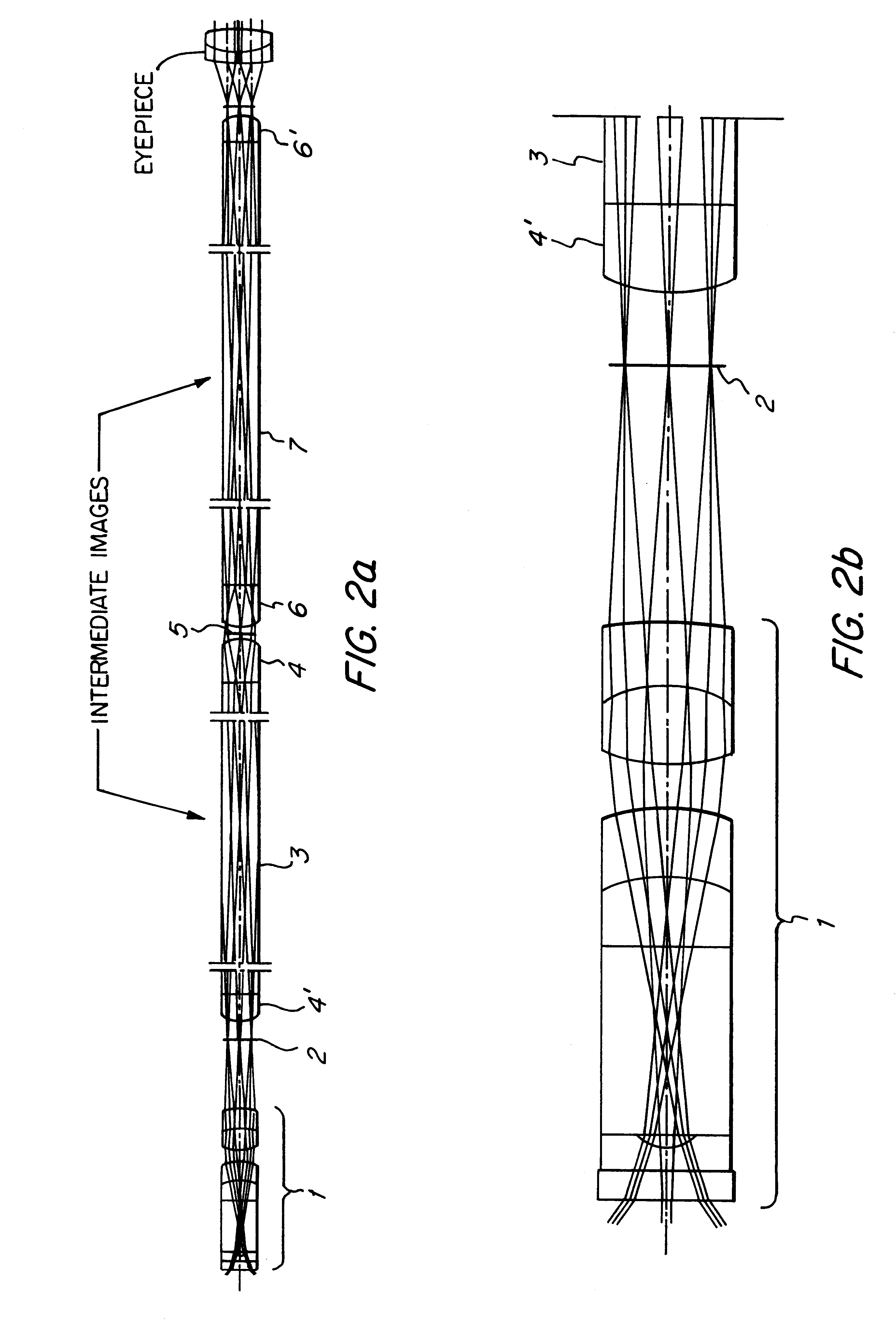
In the invention a respective plano-convex lens 4, 4' or 6, 6' is cemented on both faces of the rods 3 or 7, respectively, which are "optically thin".

FIG. 2a shows the overall structure whilst FIG. 2b illustrates the structure of the 0.degree. lens.

Either rod 3 or 7 consists of a material having an inhomogeneous refractive index whilst the lenses 4, 4' or 6, 6' consist of a material having a homogeneous refractive index.

FIGS. 3a and 4a are view of the overall structure in which a 30.degree. and a 70.degree. lens is used whilst FIGS. 3b and 4b show the structure of the respective lenses.

The following Table 5 reflects the numerical data of the reversing system in accordance with the second embodiment which provides for three image reversals:

Like in the previous embodiments, "*" denotes the materials having an inhomogeneous refractive index.

As has been set out in the foregoing, the lens 1 need not present a tangential and sagittal (lateral) field curvature--which is specified for a cer...


PUM


Abstract

An endoscope having a distally disposed lens and an optical transmission system which transmits the image of the lens to the proximal end of the endoscope is provided. The transmission system includes at least one reversing system, which includes two elements in mutual mirror-inverted arrangement. Each element includes a rod lens with planar faces and at least one optically thin lens having a planar surface. The rod lenses consist of an inhomogeneous material having a positive dispersion and an inhomogeneous refractive index in the radial direction, while the thin lenses are plano-convex lenses.

Description

The present invention relates to an endoscope in accordance with the introductory clause of Patent claim 1.PRIOR ARTAn endoscope of the claimed general type is known from the U.S. Pat. No. 4,783,154. That known endoscope comprises a distally disposed lens and an optical transmission system which transmits the image of the lens disposed on the distal end to the proximal end, i.e. to that end of the endoscope which is located outside the cavity. The transmission system includes at least one reversing system consisting of two symmetrical elements whereof each is formed by a optically thin piano-concave lens. The rod lenses, which may include, inter alia, plane faces, consist of a material having a varying or inhomogeneous refractive index.For an explanation of all the aspects not described here in more details explicit reference is made, by the way, to the U.S. Pat. No. 4,783,154 and the prior art documents listed on the cover sheet of that patent document.For the purposes of the prese...

Claims


Application Information

Patent Timeline
IPC IPC(8): G02B23/24A61B1/00G02B23/26A61B1/002
CPCG02B23/2407
Inventor LEI, FANG
Owner KARL STORZ GMBH & CO KG
Learn More