Liquid crystal apparatus, driving method thereof, and projection-type display apparatus and electronic equipment using the same

a technology of liquid crystal apparatus and driving method, which is applied in the direction of instruments, static indicating devices, etc., can solve the problems of increasing resistance and parasitic capacity of scanning signal lines, slow switching properties, and increasing wiring resistance of scanning signal lines

Inactive Publication Date: 2001-10-23
SEIKO EPSON CORP
View PDF6 Cites 41 Cited by
  • Summary
  • Abstract
  • Description
  • Claims
  • Application Information

AI Technical Summary

Problems solved by technology

Accordingly, there is the problem that the switching properties are slow not only in data signal sampling but also in pre-charging, and accordingly, study is being made regarding various circuit operations accompanying them.
Also, increased panel size means that the wiring resistance of the scanning signals lines increases.
Accordingly, the parasitic resistance and parasitic capacity in the scanning signal lines increases and becomes a load, which in turn causes problems of wiring delays.

Method used


Image

  • Liquid crystal apparatus, driving method thereof, and projection-type display apparatus and electronic equipment using the same
  • Liquid crystal apparatus, driving method thereof, and projection-type display apparatus and electronic equipment using the same
  • Liquid crystal apparatus, driving method thereof, and projection-type display apparatus and electronic equipment using the same

Examples


Embodiment Construction

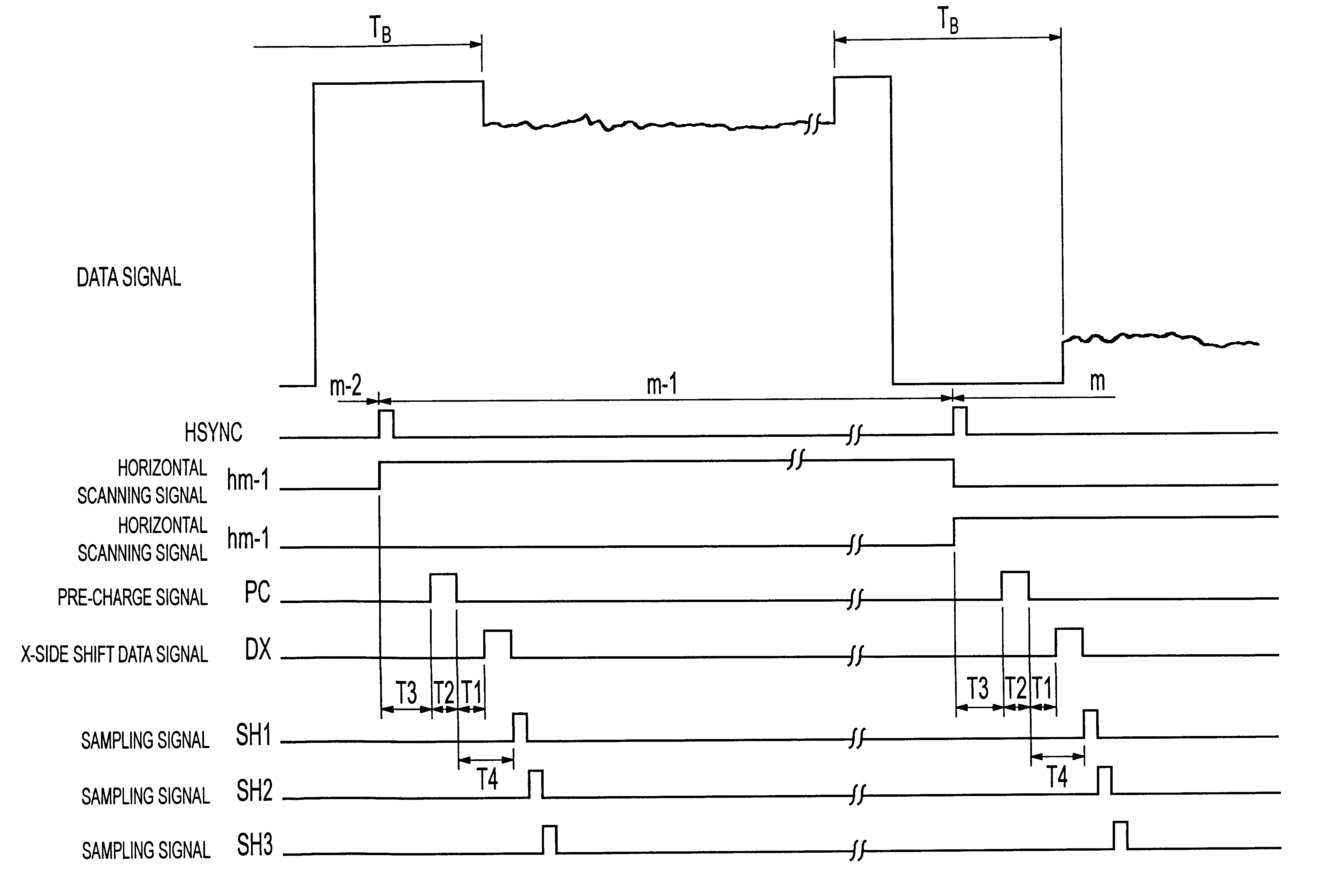
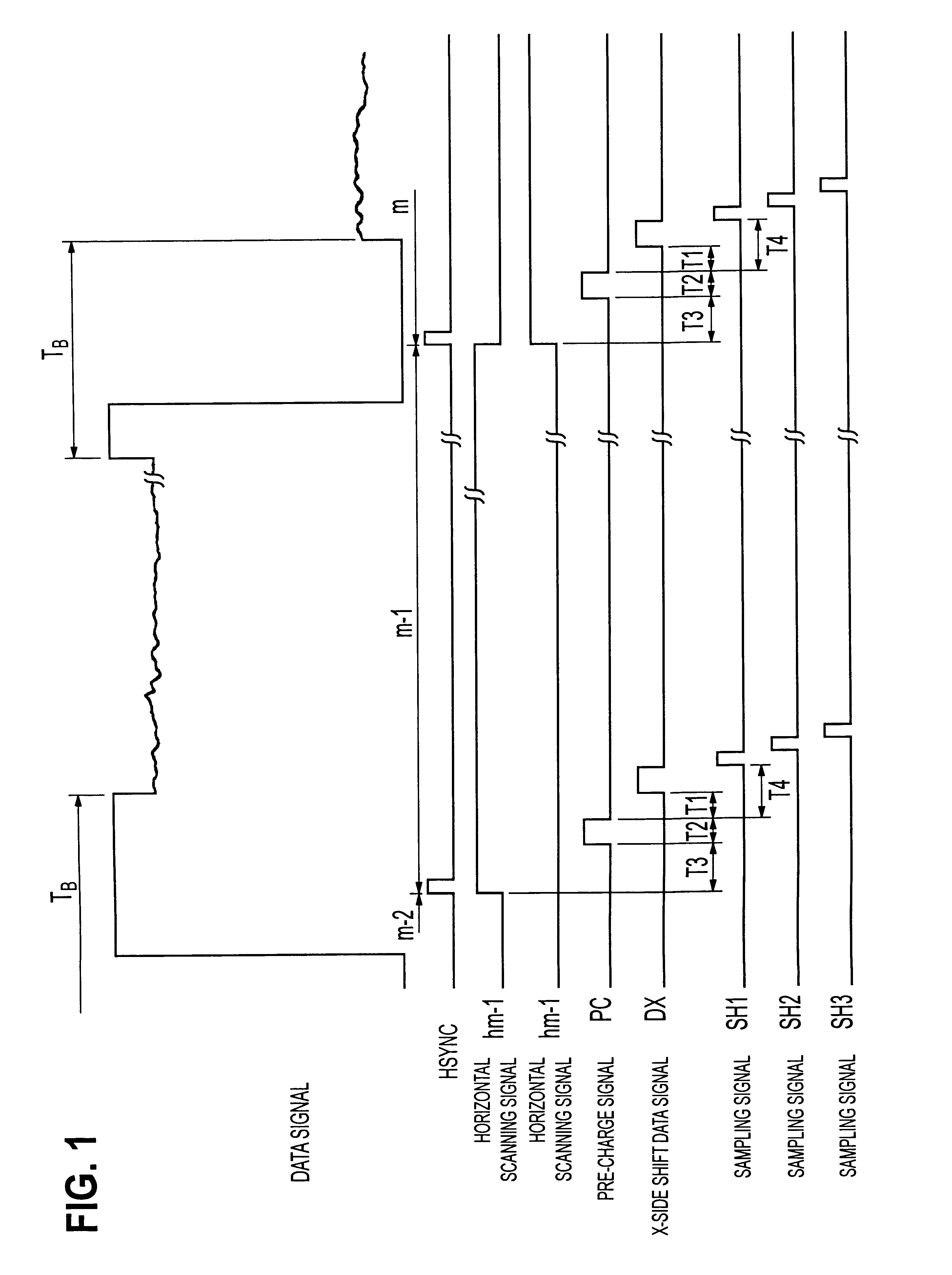
FIG. 1 is a timing chart for describing the pre-charging operation and data sampling operation in an active-matrix liquid display device according to the present invention;

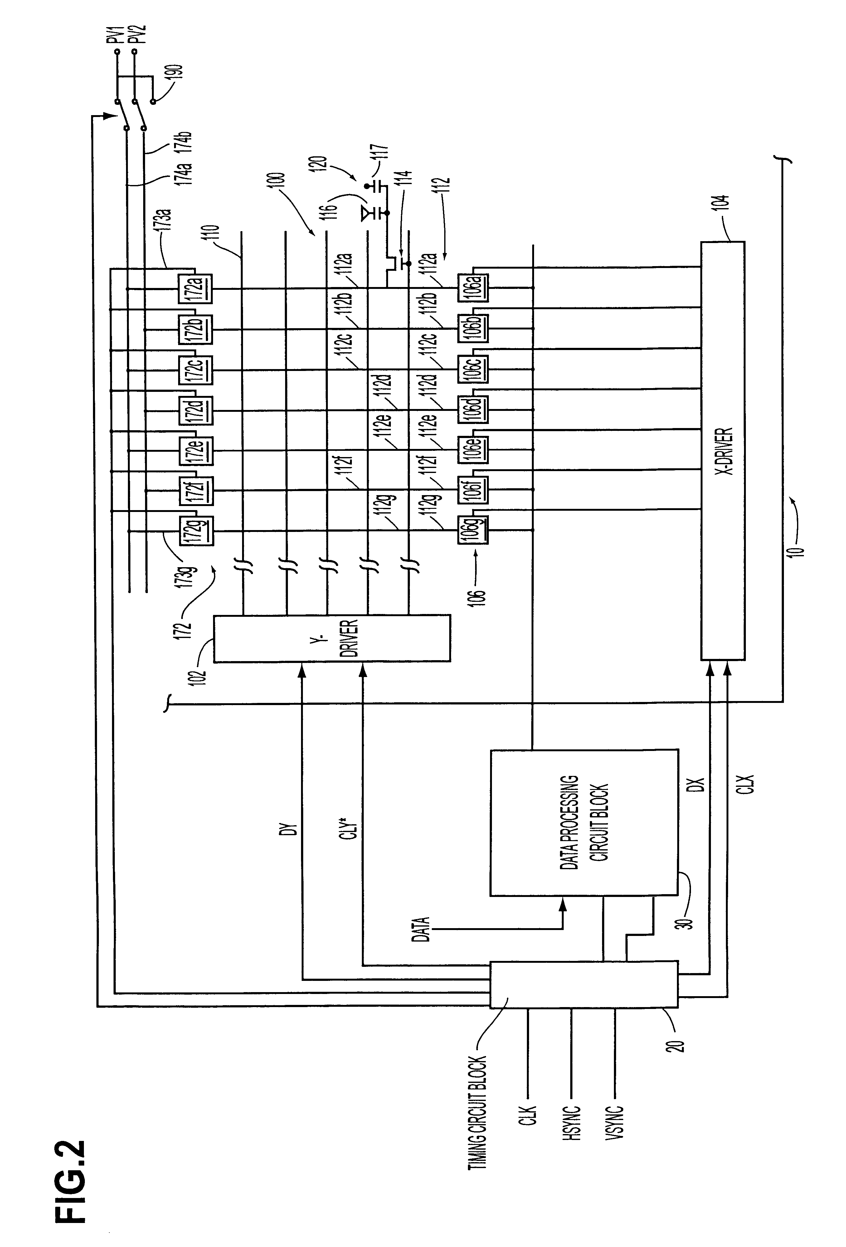
FIG. 2 is a schematic diagram of an active-matrix liquid crystal display apparatus according to a first embodiment of the present invention;

FIG. 3 is a diagram for describing the pre-charging switch and sampling switch of an active-matrix liquid crystal display apparatus according to the first embodiment of the present invention;

FIG. 4 is a timing chart for describing the operation of a Y-driver of an active-matrix liquid crystal display apparatus according to the first embodiment of the present invention;

FIG. 5 is a timing chart for describing the potential of the data signal line connected to the leading pixel;

FIG. 6 is a timing chart for describing the potential of the data signal line connected to the trailing pixel;

FIG. 7 is a block diagram of the adjusting circuit provided within the timing circuit block sho...


PUM


Abstract

A liquid crystal apparatus for preventing deterioration of image quality owing to delay of the signal transporting speed at the time of switching, due to parasitic capacity and parasitic resistance in the pre-charging signal supply path and horizontal scanning signal supply path. The time interval (T4) from the point of the end of the pre-charging period T12 within the m'th horizontal scanning period to the point of the start of the leading sampling period in the m'th horizontal scanning period has been set so as to be longer than the signal transporting delay time at the pre-charging switch (172) connected to the data signal line S1. Accordingly, the time interval (T1) from the end of the pre-charging period (T2) to the point at which the shift data signal (DX) of the X-driver (104) becomes active has been set so as to be longer than the signal transporting delay time at the pre-charging switch (172) connected to the data signal line S1. Further, the time interval (T3) from the point of the end of the (m-1)th horizontal scanning period to the point of the start of the pre-charging period (T2) set within the m'th horizontal scanning period has been set so as to be longer than the signal transporting delay of the horizontal scanning signal h(m-1) reaching the pixel A(m-1, x) positioned farthest away from the Y-driver (102).

Description

1. Field of InventionThe present invention relates to a liquid crystal apparatus, a driving method thereof, and a projection-type display apparatus and electronic equipment using the liquid crystal apparatus.2. Description of Related ArtFor example, with an active-matrix liquid crystal apparatus, action of writing data to the liquid crystal layer of each pixel is executed by line-at-a-time driving, via switching elements such as a plurality of TFTs (thin-film transistors) connected to a scanning signal line.Also, in order to eradicate unevenness in the display owing to imbalance in voltage applied to the liquid crystal, and in order to prevent deterioration and so forth of the liquid crystal due to the direct current applied to the liquid crystal, polarity inversion driving is performed, wherein the polarity of the voltage applied to the liquid crystal is inverted at a certain timing.Polarity inversion driving is a method of driving wherein voltage is applied to one end of the liqui...

Claims


Application Information

Patent Timeline
Patent Type & Authority Patents(United States)
IPC IPC(8): G09G3/36G09G3/00
CPCG09G3/3648G09G3/001G09G3/3614G09G2310/0248G09G2320/0223G09G2340/02
Inventor AOKI, TORU
Owner SEIKO EPSON CORP
Why Eureka
Try Eureka