Vehicle air conditioner

a technology for air conditioners and vehicles, applied in vehicle components, vehicle heating/cooling devices, railway heating/cooling, etc., can solve the problems of increased pressure loss, reduced air flow toward the rear seat side, and increased heat loss in the rear foot du

Inactive Publication Date: 2001-11-06
DENSO CORP
View PDF11 Cites 149 Cited by
  • Summary
  • Abstract
  • Description
  • Claims
  • Application Information

AI Technical Summary

Problems solved by technology

Thus, during the temperature control area, pressure loss is increased due to a bent air flow.
Further, because the rear foot duct is necessary to have a long distance pipe from an air conditioning unit disposed at a vehicle front side to a rear seat side, heat loss becomes larger in a rear foot duct, and temperature of air blown toward the rear seat side

Method used


Image

  • Vehicle air conditioner
  • Vehicle air conditioner
  • Vehicle air conditioner

Examples


first embodiment

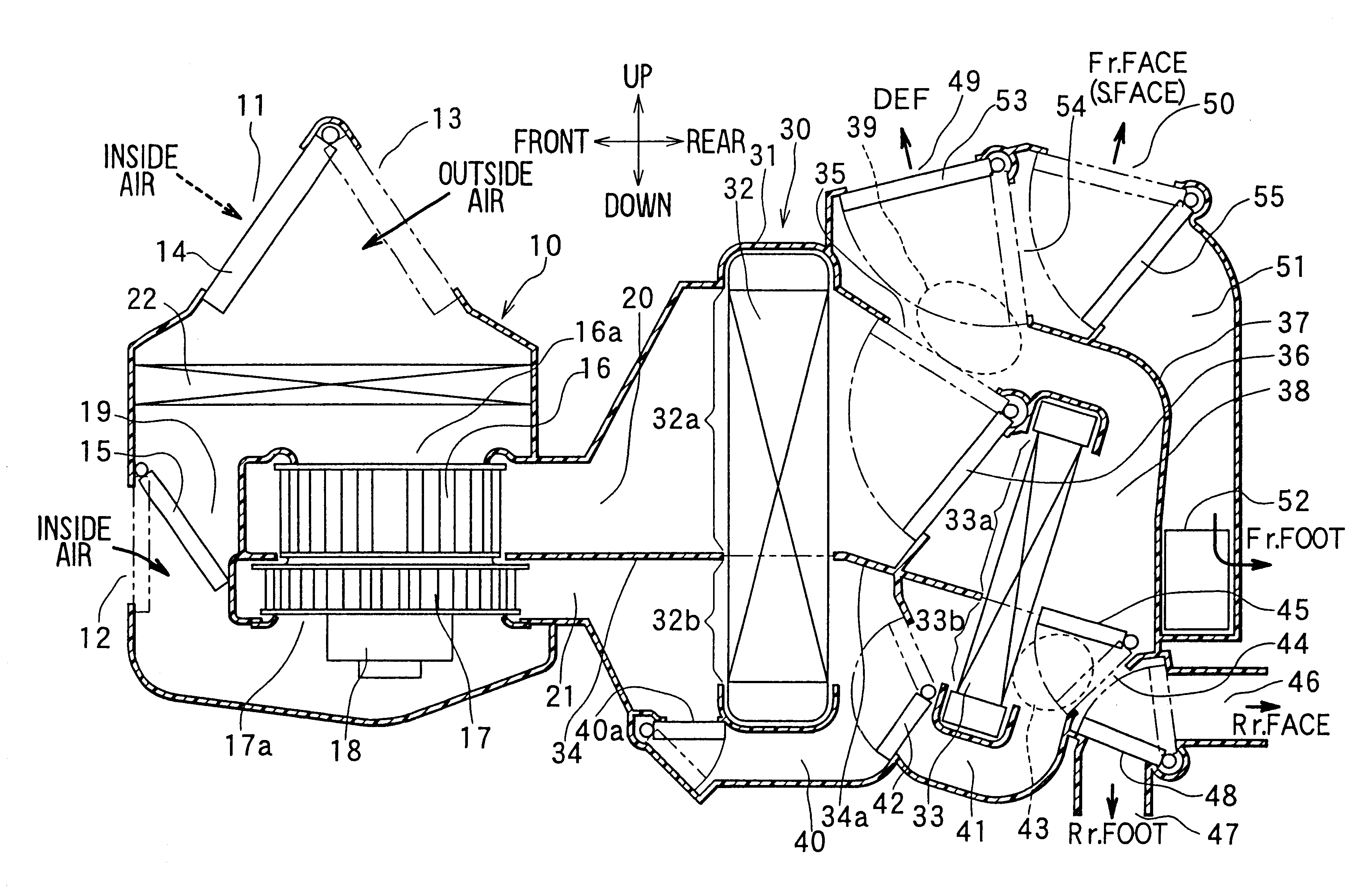
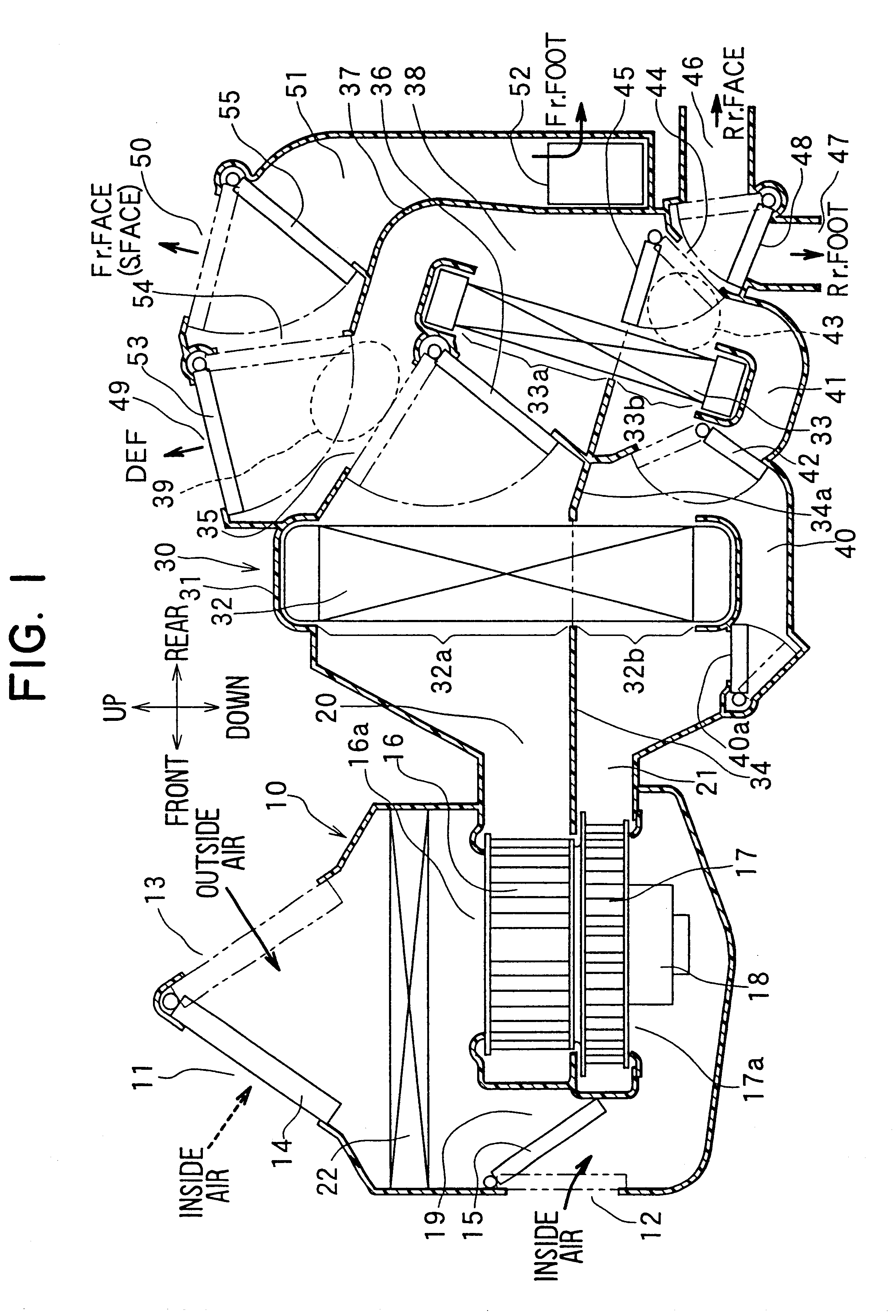
In the above-described first embodiment, the rear air-outlet mode door 48 can be operatively linked with the front air-outlet mode doors 53, 55 while the front air mixing door 36 is operatively linked with the rear air mixing door 42, so that a door driving mechanism can be made simple. In this case, the opening degree of the rear air mixing door 42 is corrected relative to the opening degree of the front air mixing door 38. Therefore, heat loss generated in the rear duct can be canceled.

For example, during the foot mode, the opening degree of the rear air mixing door 42 is corrected to a high-temperature side relative to the opening degree of the front air mixing door 36, so that a decrease of air temperature blown toward the rear foot area, due to the heat loss in the rear duct, is restricted. Further, during the face mode, the opening degree of the rear air mixing door 42 is corrected to low-temperature side relative to the opening degree of the front air mixing door 36, so that ...

second embodiment

In the second air passage 21, by adjusting the opening degree of the evaporator bypass door 40a, a ratio between an amount of cool air passing through the lower part 32b of the evaporator 32 and non-cooled air (i.e., sucked air of the blower unit) passing through the evaporator bypass passage 40 is adjusted, so that the temperature of air blown from the rear face opening 46 is adjusted. In the second air passage 21, cool air from the lower part 32b of the evaporator 32 and non-cooled air from the evaporator bypass passage 40 are mixed in an air mixing portion 80, and the mixed air approximately linearly flows from the air mixing portion 80 toward the rear face opening 46 through the rear bypass passage 41. Therefore, air blown toward the rear face opening 46 has a small pressure loss, and the air amount blowing toward the rear seat side from the rear face opening 46 is increased. Thus, in the second embodiment, cooling capacity for the rear seat side of the passenger compartment is ...

third embodiment

In the third embodiment, during the face mode, the evaporator bypass door 40a is operated to the chain line position in FIG. 8 to fully close the evaporator bypass passage 40. Therefore, air blown by the second fan 17 in the second air passage 21 passes through a lower part of the evaporator 32 to be cooled and is blown toward the front air mixing portion 39. Thus, cooling performance for the front seat side of the passenger compartment is improved.

Further, during the defroster mode, the rear door 45 is operated to the chain line position in FIG. 8 to fully close the rear foot opening 47, so that the defrosting performance for the windshield is improved as described in the first embodiment. In the third embodiment, the other portions are similar to those in the above-described first embodiment.

A fourth preferred embodiment of the present invention will be now described with reference to FIGS. 9-14. In the above-described first embodiment, during the double layer flow mode, inside ai...


PUM


Abstract

In a vehicle air conditioner, a first air passage through which outside air flows and a second air passage through which inside air flows are provided to be partitioned from each other, so that outside air in the first air passage is blown toward a front seat side of a passenger compartment from a front air outlet after passing through a first part of a heat exchanger, and inside air in the second air passage is blown toward a rear seat side of the passenger compartment from a rear air outlet after passing through a second part of the heat exchanger, during a double layer flow mode. Thus, in the second air passage, temperature of air sucked from an inside air port can be set to temperature of inside air inside the passenger compartment, while air pressure loss due to an inside air suction is decreased. As a result, in the vehicle air conditioner, air-conditioning capacity for the rear seat side is improved.

Description

This application is related to and claims priority from Japanese Patent Applications No. Hei. 11-122470 filed on Apr. 28, 1999, and No. 2000-45138 filed on Feb. 17, 2000, the contents of which are hereby incorporated by reference.1. Field of the InventionThe present invention relates to a vehicle air conditioner having a front air-blowing structure for blowing air toward a front seat side of a passenger compartment and a rear air-blowing structure for blowing air toward a rear seat side of the passenger compartment.2. Description of Related ArtIn a conventional vehicle air conditioner, for improving both heating performance for heating air blown toward the foot area of a passenger and defrosting performance of a windshield in the winter, an inside / outside air double layer flow mode (hereinafter, referred to as "double layer flow mode") is set so that circulated inside air having a high temperature is blown from a foot opening and outside air having a low-humidity is blown from a def...

Claims


Application Information

Patent Timeline
IPC IPC(8): B60H1/00B60H1/24
CPCB60H1/00664B60H1/00849B60H1/247
Inventor UEMURA, YUKIOMIYAJIMA, NORIYOSHI
Owner DENSO CORP
Why Eureka
Try Eureka