Multifaceted balanced magnetic proximity sensor

a magnetic proximity sensor and multi-faceted technology, applied in the direction of magnetic/electric field switches, electrical appliances, electric switches, etc., can solve the problems of large size of devices, inability to adjust, and require alignment,

Inactive Publication Date: 2001-11-06
OSTERWEIL JOSEF
View PDF7 Cites 224 Cited by
  • Summary
  • Abstract
  • Description
  • Claims
  • Application Information

AI Technical Summary

Problems solved by technology

These devices are substantial in size and are therefore undesired for some applications.
The limitations of this approach include that the pivoting armature is a moving part, that there is the necessity of forming several relatively precise parts, and that it requires alignment during fabrication.
However, this embodiment is very sensitive as to the relative position of the magnet and the switch and will require a complicated alignment procedure in the course of production.
It does not meet the objective of having one of the two devices small and unobtrusive.
Other approaches, like U.S. Pat. No. 4,858,622 (Osterweil), have the deficiency of inactive sensing of the proximity sensor's normal state, as well as inconvenient shunt access.
If a balanced magnetic pole array already includes shunts, removal of at least one shunt from the magnetic pole array will also disrupt the balance.

Method used


Image

  • Multifaceted balanced magnetic proximity sensor
  • Multifaceted balanced magnetic proximity sensor
  • Multifaceted balanced magnetic proximity sensor

Examples


embodiment 100

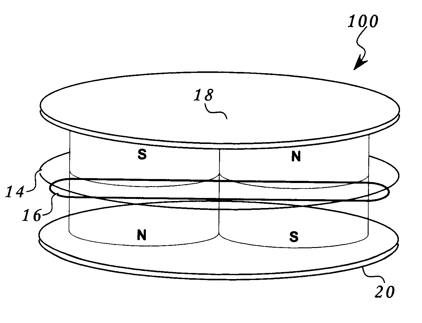
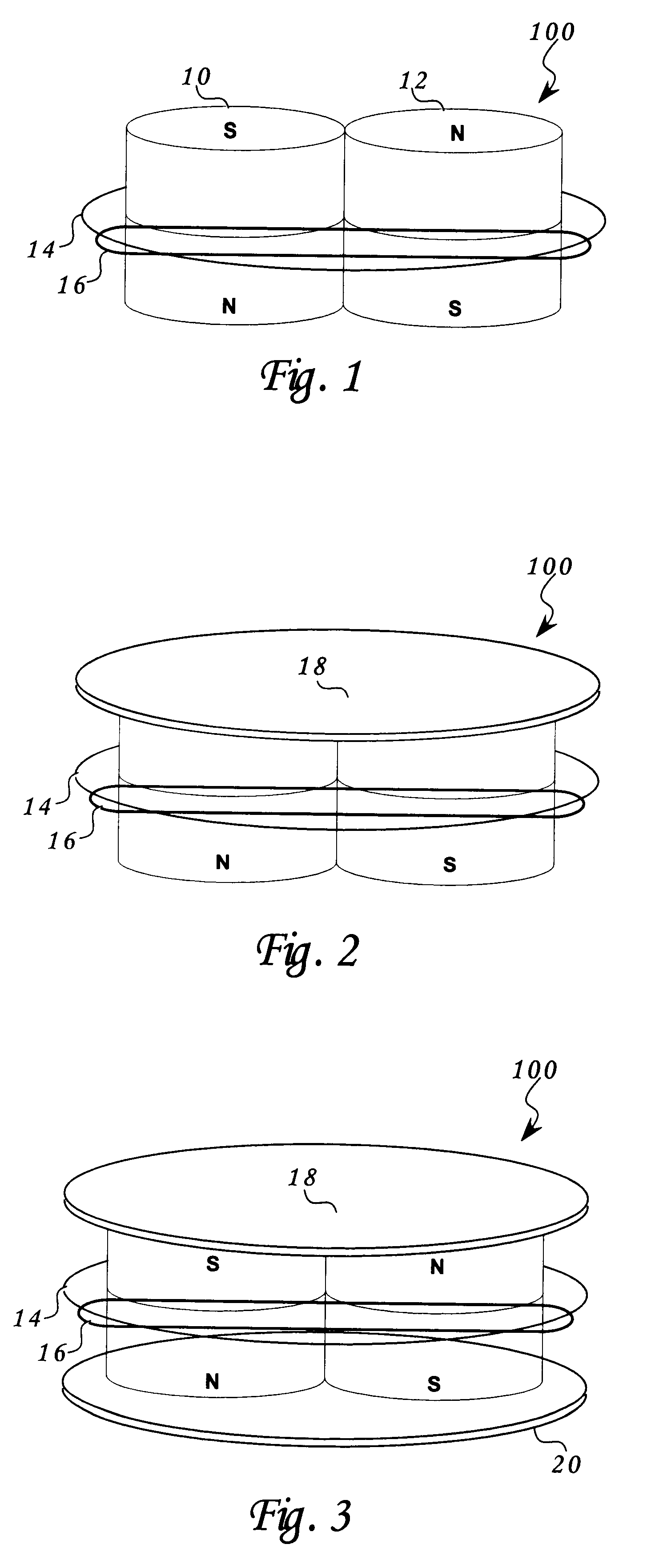
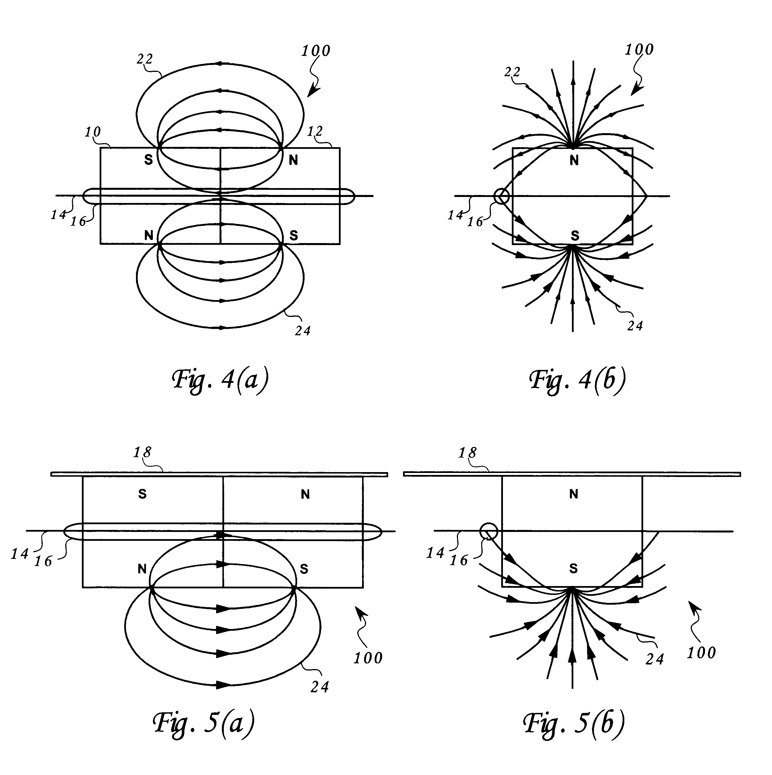
The magnetic pole array of the instant invention embodiment 100 is shown in FIG. 1. The magnetic pole array consists of two magnets (10) and (12) each with a North Pole and a South Pole. This magnetic pole array is equivalent to a four pole axially magnetized magnet shown in FIG. 21. The magnets are positioned next to each other so that the South Pole of one faces the same direction as the North Pole of the other. In this position, the two magnets attract and, in fact, can adhere to each other without external support. The attraction forces are due to the magnetic flux (22) and (24) of FIG. 4(a) that flows between the poles through two air gaps (upper and lower). A plane that is defined by the center cross section of the two magnets, the "equatorial" plane (14), exhibits a zone where the horizontal magnetic field is canceled (the field vector sum approaches zero). The canceling of the magnetic field shown in FIG. 4(a), is due to the equal and opposing field vectors, a canceling flux...

embodiment 102

FIG. 7(a) and FIG. 7(b) illustrate embodiment 102 of the proximity sensor configuration where the reed switch is placed above the equatorial plane where the field is not completely balanced. The introduction of a shunt, FIG. 8(a) and FIG. 8(b), at a location above the top magnetic pole array poles will reduce the magnetic field emanating from these poles. This field will diminish as the shunt is brought closer to the poles. At some point, before reaching the poles, the field emanating from the top two poles will balance the field emanating from the bottom two poles at the location of the sensor (16) thus the reed switch will be deactivated.

FIG. 9(a) and FIG. 9(b) illustrate embodiment 104 of the proximity sensor configuration that deactivates the reed switch when the shunt approaches the poles from a distance as in embodiment 102 in FIGS. 7(a), 7(b), 8(a), and 8(b). This approach balances the magnetic pole array by a second shunt applied at a distance to the bottom poles while the r...

embodiment 116

is an example of a combinational logic function and is shown in FIGS. 22 and 23. FIG. 22 illustrates a four-magnet (66), (68), (70), and (72) magnetic pole array configuration that is designed to perform a logical AND function. The sensor (16) is placed on the equatorial plane (14) substantially symmetrical to and between the two dual magnet sets (66), (68) and (70), (72) respectively. The magnetic field is balanced and the flux density approaches zero at the location of the sensor (16) that is therefore not activated.

FIG. 23 illustrates embodiment 116 with the addition two shunts (18a and 18b). While the two shunts (18a and 18b) are located on top of the two dual magnet sets (66), (68) and (70), (72) respectively, the magnetic pole array is unbalanced and the sensor is active. The removal of either shunt (18a or 18b) will reduce the unbalance by approximately a factor of two but the residual imbalance will keep the sensor active. Only the removal of both shunts (18a and 18b) will b...


PUM


Abstract

An apparatus and method of proximity switch / sensor based generally on a balanceable magnetic pole array. The magnetic pole array contains at least four poles with optional ferromagnetic shunt(s). The proximity of a shunt to a magnetic pole array determines whether the array is balanced or unbalanced. A balanced array is one with a zone where the vector sum of magnetic fields emanating from the array's poles can be made to approach zero. A sensor such as a reed switch is placed in the balanced zone. When the balance of the array is disturbed by the application of one or multiple shunts, the resulting finite magnetic field vector along with the resulting magnetic flux, activates the sensor. This approach can be implemented in a variety of array structures that offer implementation of a variety of logical functions. Multiple shunts and their proximity to the array are used as the logical function's inputs and the sensor's state as the logical function's output.

Description

This invention relates to a magnetic proximity sensor with novel features. It is based on a magnetic pole array, which exhibits a balanced magnetic field in one state and unbalanced magnetic field in the opposite state. The transition from one state to the other is accomplished with a minimal sized ferromagnetic substance(s) (magnetic shunt) either added or removed from strategic places on the magnetic pole array. The sensors may perform logical functions, primarily when multiple shunts are used.DESCRIPTION OF PRIOR ARTMagnetic proximity sensing has been used for many years. There are many different magnetic proximity sensor concepts in use today including static threshold, transient, electromagnetic, and solid-state. The list of prior art for magnetic proximity sensing applications is very long and includes security systems, automation, instrumentation, etc.The magnetic proximity sensor category of the instant invention is best characterized as the static threshold type using a mag...

Claims


Application Information

Patent Timeline
Patent Type & Authority Patents(United States)
IPC IPC(8): H01H36/00
CPCH01H36/002H01H36/0046
Inventor OSTERWEIL, JOSEF
Owner OSTERWEIL JOSEF
Why Eureka
Try Eureka