
Method and device for diagnosis for vehicle

Inactive Publication Date: 2001-11-06
HONDA MOTOR CO LTD
View PDF13 Cites 46 Cited by
  • Summary
  • Abstract
  • Description
  • Claims
  • Application Information

AI Technical Summary

Benefits of technology

According to the vehicle diagnostic method and apparatus thus configured, issue of a forced activation signal associated with a particular diagnostic item can be stopped not only when the particular diagnostic item is passed, but also after the forced activation signal has been issued for a predetermined period of time, thereby preventing the forced activation signal for the particular diagnostic item from being continuously issued, and hence from hindering diagnoses for the other items.

Problems solved by technology

It is therefore impossible to diagnose a subsequent item before the previous item is diagnosed as being passed or failed.
This causes long compulsory working-hours of the operator.
However, for example, a diagnosis of a function for controlling valve opening and closing timing in accordance with such parameters as the vehicle running speed and the engine speed, and a diagnosis of an evaporation system for collecting fuel gas evaporated from a fuel tank and supplying it to the engine when predetermined operating conditions are satisfied (hereinafter, referred to as an "EVP Diagnosis") are very difficult to be carried out, because it is difficult to realize such running condition in a limited diagnostic process or environment that said function and the evaporation system actually operate.
However, the ECU is not able to issue plural forced activation signals at a time because of its restricted functionality, and the contents and destination of each forced activation signal vary depending on the diagnostic target.
Thus, the second forced activation signal cannot be issued until completion of the diagnosis of the first item, and this causes a problem that diagnoses of the other items cannot be executed unless the diagnosis of the first item passes.
In such a case, if a diagnosis item or items susceptible to the fuel concentration in the mixed gas are included as other diagnostic items, these diagnostic items cannot be diagnosed correctly.

Method used


Image

  • Method and device for diagnosis for vehicle
  • Method and device for diagnosis for vehicle
  • Method and device for diagnosis for vehicle

Examples


Embodiment Construction

Referring now to the drawings, the present invention will be described in detail below.

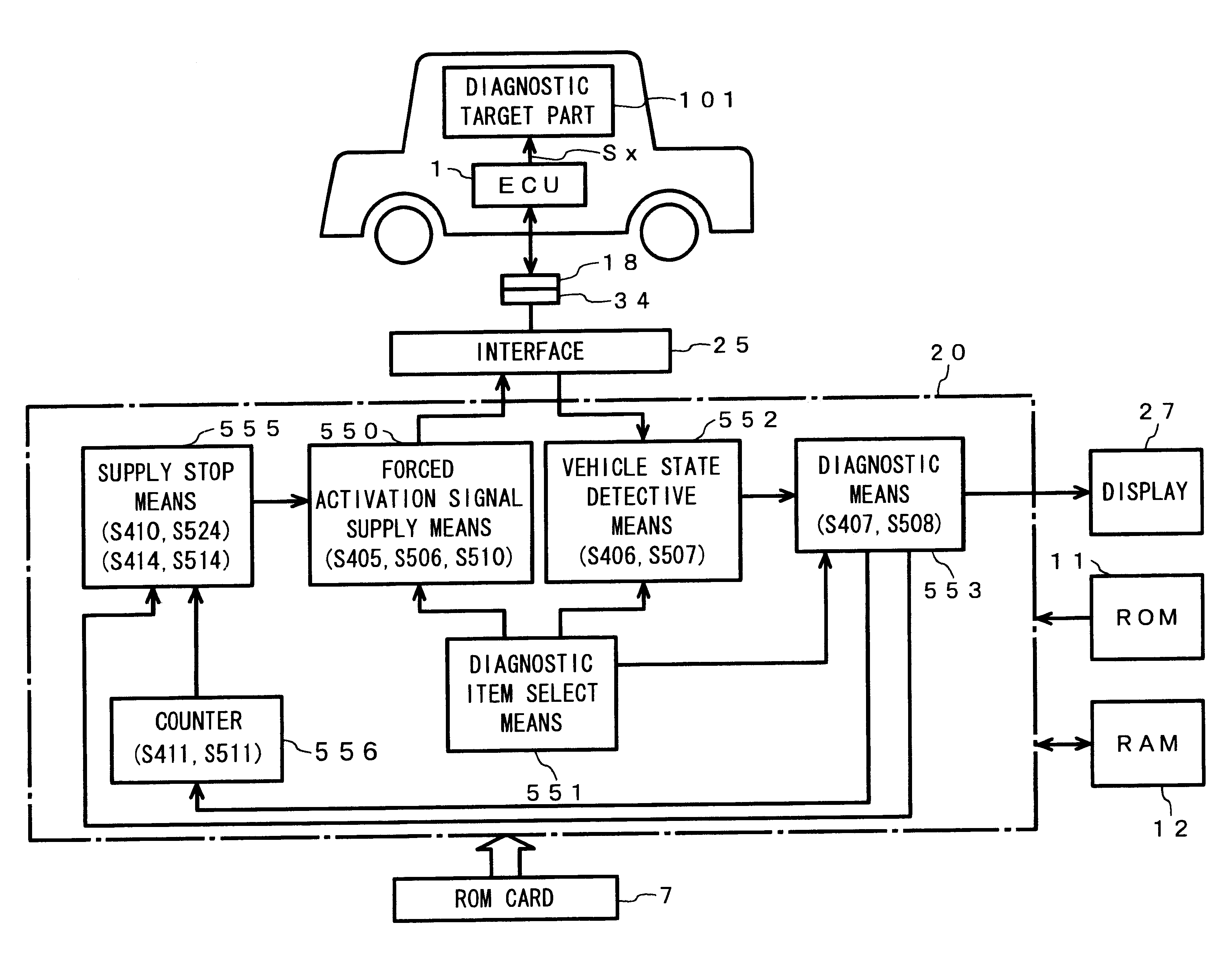
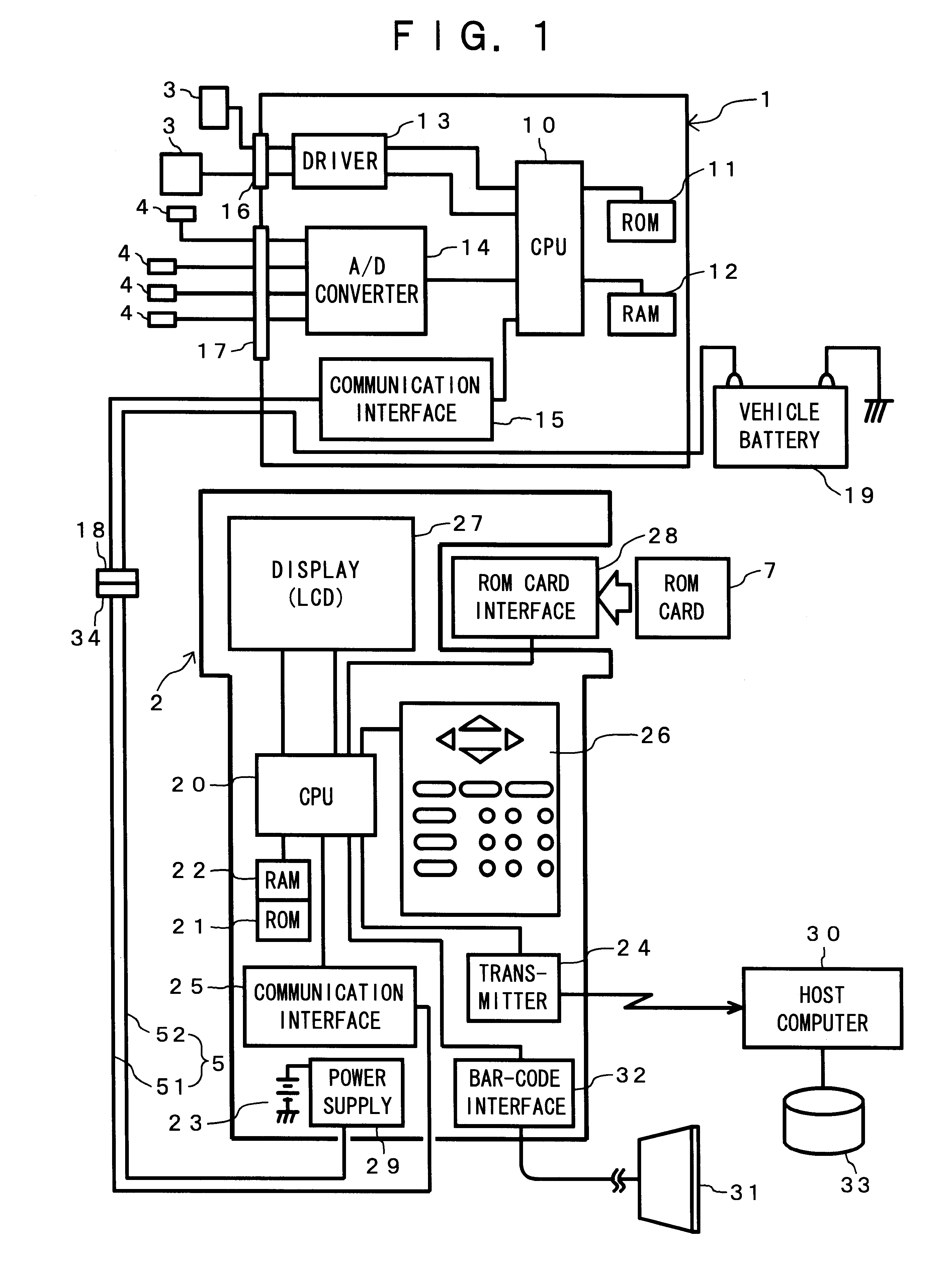
In FIG. 1, the ECU 1 is constituted of a CPU 10, a ROM 11, a RAM 12, a driver 13, an A / D converter 14, and a communication interface 15. The ECU 1 is connected to peripherals devices through connectors 16 and 17. For example, actuators 3 are connected with the connector 16, while various types of sensors and switches 4 are connected with the connector 17. The ECU 1 is also connected by a connector 18 to a communication cable 5 of the vehicle diagnostic apparatus 2 through a connector 34.

Signals from each sensor 4 or the like are input to the ECU 1. In the ECU 1, the signals are converted by the A / D converter 14 into digital signals and read into the CPU 10. The signals read in the CPU 10 are processed with control data stored in the ROM 11 and the RAM 12 according to a control program stored in the ROM 11. The CPU 10 provides a command signal to the driver 13 in accordance with the processing resu...


PUM


Abstract

A method and device for diagnosing a vehicle, in which a forced activation signal Sx is supplied to a diagnostic target part through an ECU. A current state of the detected diagnostic target part is compared with a state predicted when the forced activation signal Sx is given to diagnose the diagnostic target part. The forced activation signal Sx when the diagnostic target part is judged to be good, or after a predetermined time has elapsed since issue of the signal Sx was initiated.

Description

1. Field of the InventionThis invention relates to vehicle diagnostic method and an apparatus therefor, and in particular, to the vehicle diagnostic method and apparatus for communicating with an electronic control unit mounted on a vehicle to diagnose the vehicle based on the communication results. More specifically, it relates to the vehicle diagnostic method and apparatus, in which a forced activation signal is issued so that each part of the vehicle will show an expected state, whereby each diagnostic item is judged to be good or bad based on whether or not an actual state of the part is in the expected state.2. Description of the Related ArtTo improve engine control functions, an electronic control unit (ECU) with a microcomputer has been used in recent years for executing control programs, such as control of ignition timing in an engine, control of valve opening and closing timing, and / or control of fuel injection in an electronic fuel injector (EFI) for an automobile (hereina...

Claims


Application Information

Patent Timeline
IPC IPC(8): G01M15/05G01M15/04G05B23/02G01M17/007
CPCG01M15/05
Inventor SASAKI, KAZUMUNEHASHIMOTO, AKIRA
Owner HONDA MOTOR CO LTD
Features
  • Generate Ideas
  • Intellectual Property
  • Life Sciences
  • Materials
  • Tech Scout
  • Unparalleled Data Quality
  • Higher Quality Content
  • 60% Fewer Hallucinations
Learn More