Method of bonding glass members
a glass member and glass technology, applied in the field of glass member bonding, can solve the problems of metal film damage, easy peeling off of the bonding surface, failure to act as a reflecting layer,
- Summary
- Abstract
- Description
- Claims
- Application Information
AI Technical Summary
Benefits of technology
Problems solved by technology
Method used
Image

Examples
first specific example
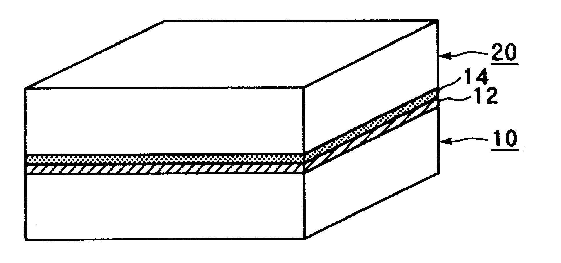
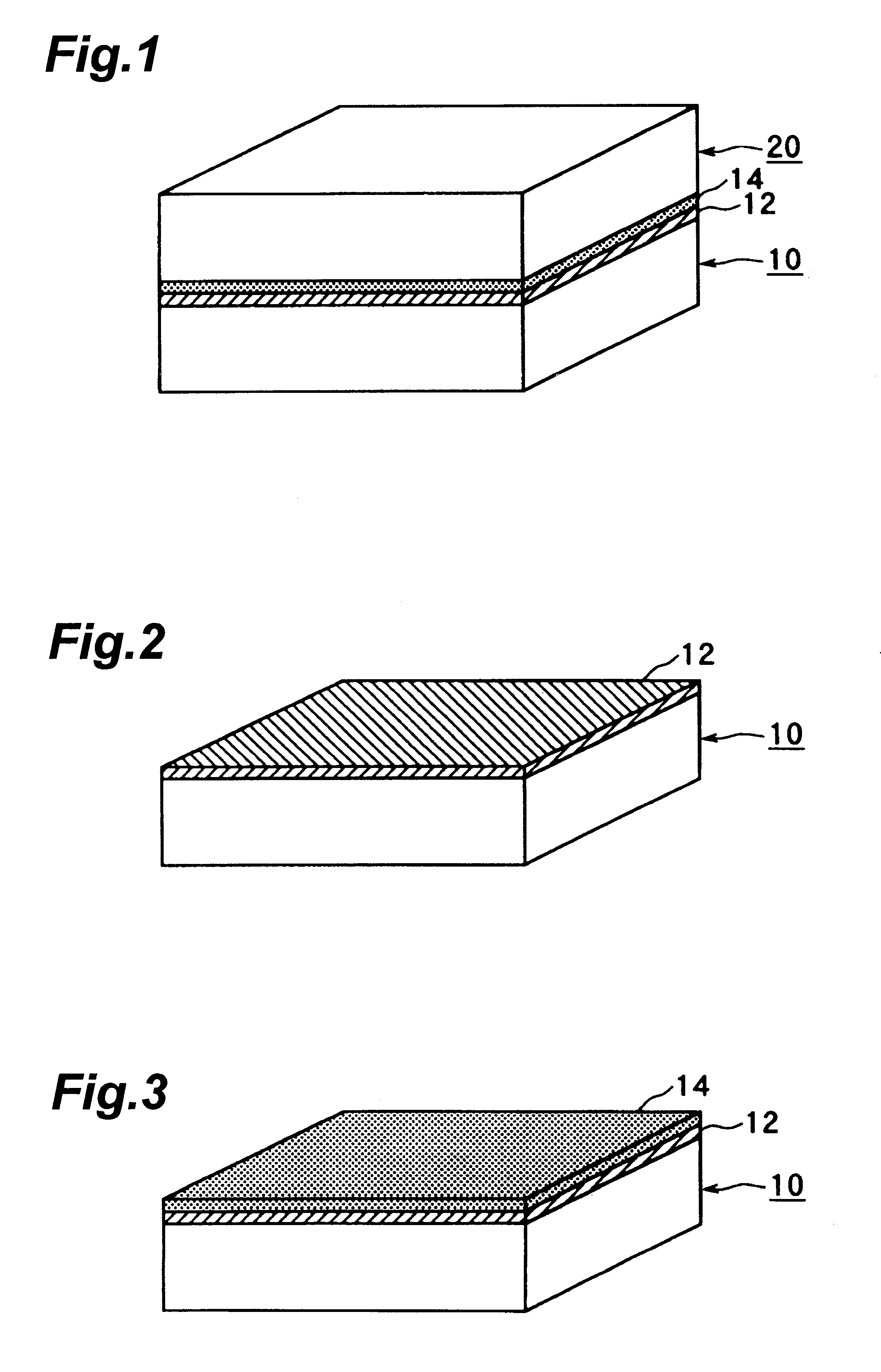
The first specific example is a method of making an optical window having a stripe-like reflecting layer in which the method of bonding glass members in accordance with the embodiment of the present invention is used. For making the optical window having a stripe-like reflecting layer, a planar glass member 10 is initially washed, and then Cr is vapor-deposited on one of main surfaces thereof by use of CVD technique, so as to form a Cr film 12 having a thickness of about 1000 .ANG.. As a result, the planar glass member 10 yields a structure such as that shown in FIG. 2.
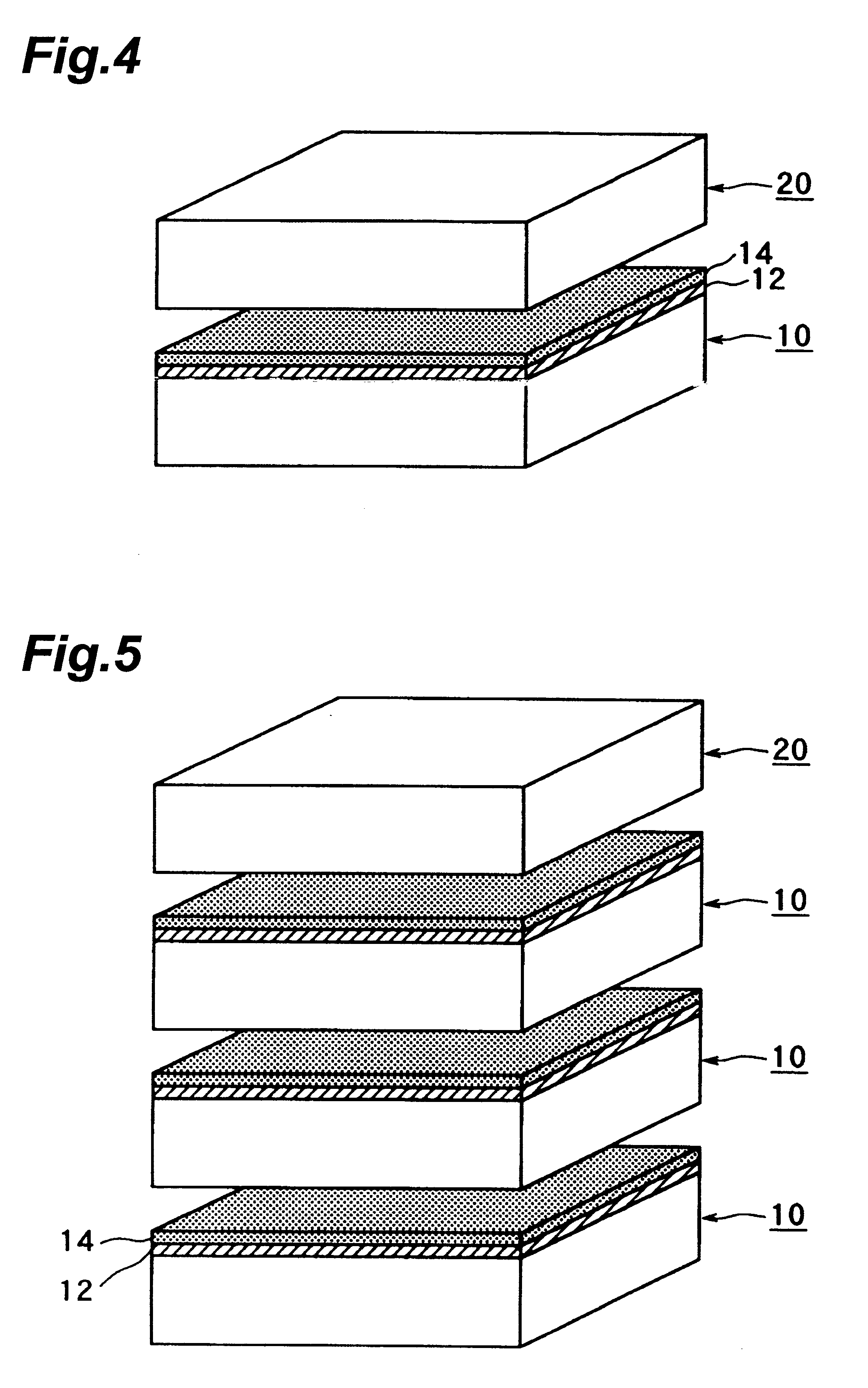
Subsequently, an SiO.sub.2 film 14 is formed on the Cr film 12. As explained in the column of the first step in the above-mentioned embodiment, the SiO.sub.2 film 14 is formed by vapor-depositing SiO.sub.2 on the Cr film 14 by use of CVD technique. The planar glass member 10 formed with the SiO.sub.2 film 14 yields a structure such as that shown in FIG. 3.
Subsequently, a number of planar glass members 10, each formed ...
second specific example
The second specific example is a method of making an optical window having a grating-like reflecting layer by using the method of bonding glass members in accordance with the embodiment of the present invention. For forming the optical window having the grating-like reflecting layer, the optical window 30 having the stripe-like reflecting layer prepared in the first specific example is used. On one of the main surfaces of the optical window 30 having the stripe-like reflecting layer, a Cr film 12 and an SiO.sub.2 film 14 are successively formed by use of CVD technique. The Cr film 12 and SiO.sub.2 film 14 each have a thickness of about 1000 .ANG.. The optical window 30 having the stripe-like reflecting layer and one of its main surfaces formed with the Cr film 12 and SiO.sub.2 film 14 would have a form such as that shown in FIG. 12.
Subsequently, a number of optical windows 30, each having a stripe-like reflecting layer and formed with the Cr film 12 and the SiO.sub.2 film 14, are st...
third specific example
The third specific example is a method of making an electron tube utilizing the method of bonding glass members in accordance with the embodiment of the present invention. This example is similar to the above-mentioned first specific example until after the Cr film 12 and the SiO.sub.2 film 14 are formed on the planar glass member 10.
Then, lithography technique is used for etching the Cr film 12 and SiO.sub.2 film 14 into their predetermined forms. HF or the like may be used for etching SiO.sub.2, whereas a mixture of cerium(IV) ammonium nitrate and perchloric acid and water or a mixture of red prussiate and NaOH (or KOH) and water may be used for etching Cr. As a result of etching, the planar glass member 10 would have a form such as that shown in FIG. 16.
After the etching, an electrode metal material 16 for a cathode or anode is formed into a predetermined shape by CVD technique or another vapor deposition technique. Here, examples of the electrode metal material 16 include Ni, Mg...
PUM
| Property | Measurement | Unit |
|---|---|---|
| thickness | aaaaa | aaaaa |
| coefficient of thermal expansion | aaaaa | aaaaa |
| temperature | aaaaa | aaaaa |
Abstract
Description
Claims
Application Information
 - R&D
- Intellectual Property
- Life Sciences
- Materials
- Tech Scout
- Unparalleled Data Quality
- Higher Quality Content
- 60% Fewer Hallucinations
Browse by: Latest US Patents, China's latest patents, Technical Efficacy Thesaurus, Application Domain, Technology Topic, Popular Technical Reports.
© 2025 PatSnap. All rights reserved.Legal|Privacy policy|Modern Slavery Act Transparency Statement|Sitemap|About US| Contact US: help@patsnap.com