Helical gear

a gear and helical technology, applied in the direction of gearing, lifting equipment, electrical control, etc., can solve the problems of linear compression or deformation of the spring clips, affecting the running characteristics and positioning precision of the slide, and affecting the accuracy of the positioning

Inactive Publication Date: 2001-11-20
LEICA GEOSYSTEMS AG
View PDF9 Cites 5 Cited by
  • Summary
  • Abstract
  • Description
  • Claims
  • Application Information

AI Technical Summary

Problems solved by technology

If, on the other hand, the axial guiding of the slide defines the displacement path vertically and laterally, there occur, in particular in the case of very precise slide guides, distortions between the driven nut and the slide.
Distortions of this type considerably impair the running characteristics and the positioning precision of the slide.
In this case, linear compression or deformation of the spring clips in the case of resistance between the spindle drive and slide guide or in the case of relatively high driving frequencies cannot be ruled out.
The frictional torque which can be transmitted to the nut from the rotation of the spindle is therefore very small, with the result that only very small mutual rotatory reactions are produced.

Method used


Image

  • Helical gear
  • Helical gear
  • Helical gear

Examples


Embodiment Construction

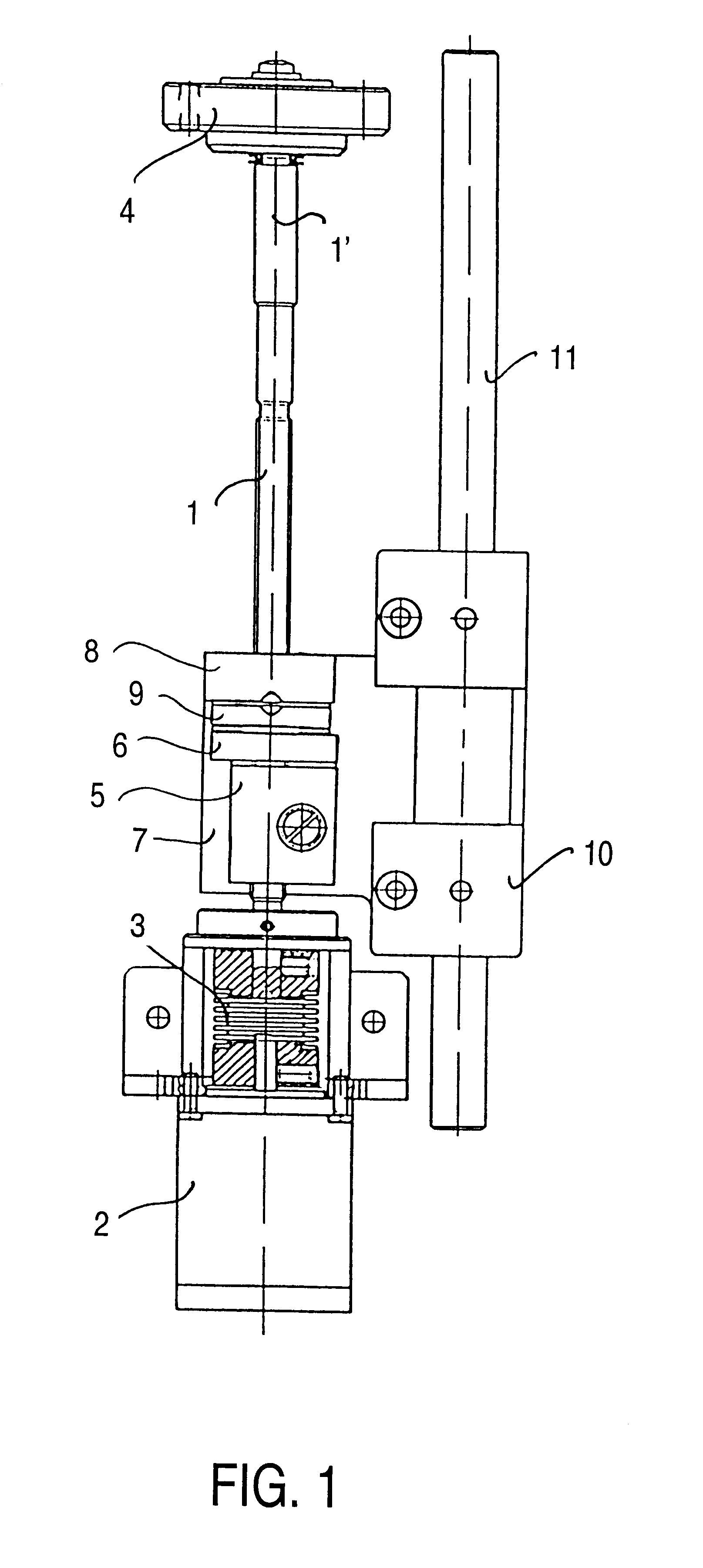
In FIG. 1, a spindle 1 is driven by a stepping motor 2 which is connected to the spindle 1 via a shaft coupling 3. At its other end, the spindle 1 runs in a ball bearing 4. The shaft coupling compensates for any alignment deviations between the spindle axis 1' and the motor axis.

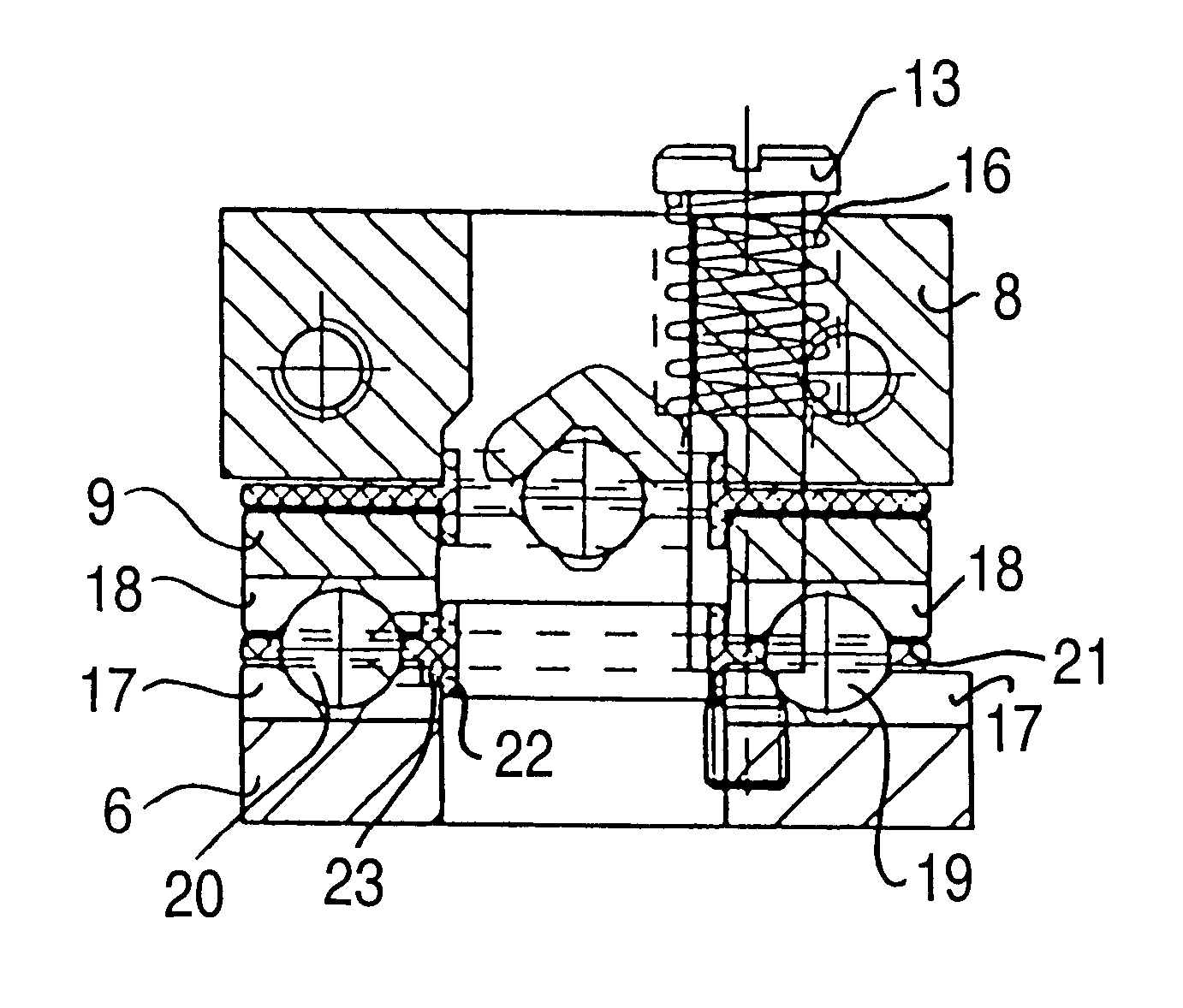
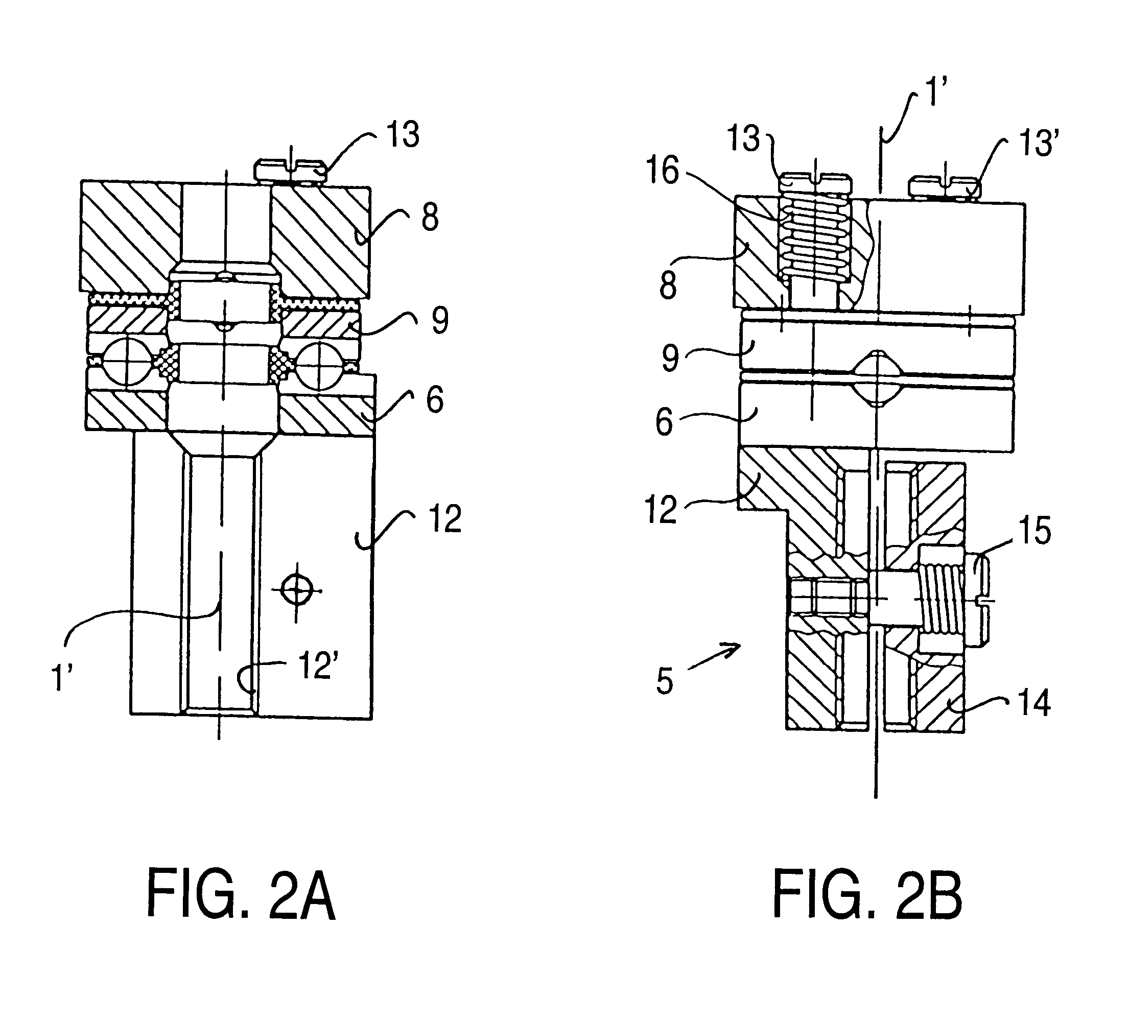
A spindle nut 5 which has a bearing plate 6 is coupled to the spindle 1. A further bearing plate 8 is fastened to a slide 7. Between the bearing plates 6 and 8 is an intermediate plate 9 which can be tilted about two axes, which are to be described later, and can be displaced along these axes. The slide 7 is connected to a pretensioned, highly precise ball guide 10 which runs along a cylindrical rod 11. The bearing brackets of the rod 11, the ball bearing 4 and the motor 2 are not illustrated. They are aligned in such a manner that the spindle 1 and the rod 11 are parallel to each other and lie in one plane. The aim is for the spindle 1 to pass through the mass center of gravity of the slide 7 in order to av...


PUM


Abstract

Screw mechanism having a spindle (1) which is secured in the axial direction and has a spindle axis (1'), and a spindle nut (5) which is connected to a slide (7) which can be driven and is guided in the axial direction, a joint being provided between the spindle nut (5) and the slide (7) in order to compensate for relative transverse movements and tilting between the spindle nut (5) and slide (7), said joint being formed symmetrically to the spindle axis (1') and having two joint axes which are perpendicular to each other, intersect on the spindle axis (1') and are assigned at one end to the transverse movement of a bearing plate (6), which is connected to the spindle nut (5), and at the other end to the transverse movement of a bearing plate (8), which is connected to the slide (7), and said joint containing an intermediate plate (9) via which the bearing plates (6, 8) are connected pivotably to each other in order to compensate for any tilting of their joint axes. The joint axes are each formed by two balls (19, 20; 19', 20') which are arranged aligned with one another on opposite sides of the spindle axis (1'), are mounted in mutually opposite prism grooves (17, 18; 17', 18') in the bearing plates (6, 8) and the intermediate plate (9), and bear against one another under spring pressure (13, 16; 13', 16').

Description

1. Field of the InventionThe invention relates to a helical gear having a spindle which is secured in the axial direction and has a spindle axis, and a spindle nut which is connected to a slide which can be driven and is guided in the axial direction, a joint being provided between the spindle nut and the slide in order to compensate for relative transverse movements and tilting between the spindle nut and slide, said joint being formed symmetrically to the spindle axis and having two joint axes which are perpendicular to each other, intersect on the spindle axis and are assigned at one end to the transverse movement of a bearing plate, which is connected to the spindle nut, and at the other end to the transverse movement of a bearing plate, which is connected to the slide, and said joint containing an intermediate plate via which the bearing plates are connected pivotably to each other in order to compensate for any tilting of their joint axes.2. Description of the Related ArtHelic...

Claims


Application Information

Patent Timeline
Patent Type & Authority Patents(United States)
IPC IPC(8): F16H25/24F02D41/40F16H1/00
CPCF16H25/24Y10T74/18728Y10T74/19902F16H2025/2445
Inventor KRANZ, GERHARDCREMA, ROLFSCHMIDT, PETER
Owner LEICA GEOSYSTEMS AG
Why Eureka
Try Eureka