Bearing support system for a printing press having cantilevered cylinders

a technology of bearing support and printing press, which is applied in the direction of printing blankets, rotary letterpress machines, rotary lithographic machines, etc., can solve the problems of affecting the cost effectiveness of the press, and affecting the printing quality of the press

Inactive Publication Date: 2001-11-20
SHANGHAI ELECTRICGROUP CORP
View PDF44 Cites 31 Cited by
  • Summary
  • Abstract
  • Description
  • Claims
  • Application Information

AI Technical Summary

Problems solved by technology

Unfortunately, the process of changing the impression sleeve is very labor intensive and time consuming, and thus there is considerable down time for the press.
As outlined above, this is a very time consuming process and seriously undermines the cost effectiveness of the press when the press is being used on relatively small jobs.
Unfortunately, in addition to other shortcomings, each of the prior art devices requires some means of temporary cylinder support in order to effectuate the changeover of the impression sleeve.
In addition, each of the prior art devices requires that at least one of the bearing assemblies be completely disconnected from the cylinder shaft, and thus, neither of these approaches provides a cost effective solution to the problems outlined above.
Another problem with prior art printing presses is that all of the rotating cylinders in the machine are mechanically connected to a single drive shaft system, which creates a number of inherent drawbacks For example, all of the rotating cylinders and rollers in a printing press are typically connected to a common drive system, which consist of an extensive collection of drive shafts, gearboxes and pulleys, all of which is designed to spin all of the cylinders in the press at the same peripheral speed.
Because all of the cylinders must have access to the same drive system, the placement of the cylinders relative to each other is severely constrained, which adds to the difficulty in changing impression sleeves on the plate cylinders.
Moreover, on large presses there is noticeable lash in the drive system, which causes registration and vibration problems, both of which negatively impact print quality.
Still another problem is the difficulty m maintaining acceptable print quality when longer cylinders are used.
For example, because the outer end of a cantilevered cylinder may deflect, it is difficult to maintain even printing pressure along the length of the cylinder.
Such a problem is of course exacerbated when longer print cylinders are used.
Uneven cylinder pressure causes web wrinkling and web migration.

Method used


Image

  • Bearing support system for a printing press having cantilevered cylinders
  • Bearing support system for a printing press having cantilevered cylinders
  • Bearing support system for a printing press having cantilevered cylinders

Examples


Embodiment Construction

The embodiments described herein are not intended to be exhaustive or to limit the invention to the precise form disclosed. They have been chosen and described in order to best explain the principles of the invention and its practical use in order to enable others skilled in the art to follow its teachings.

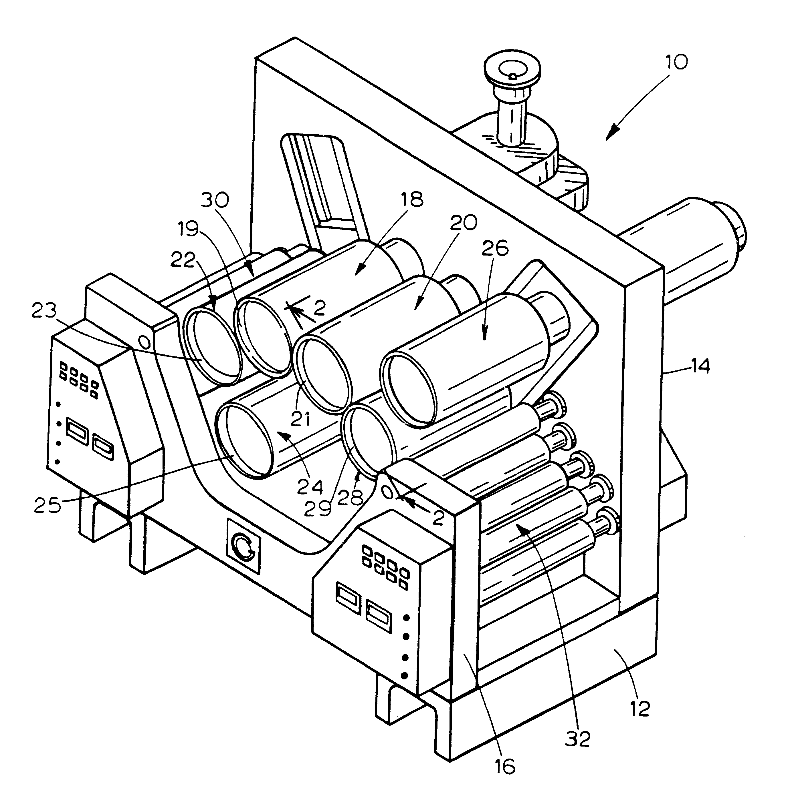
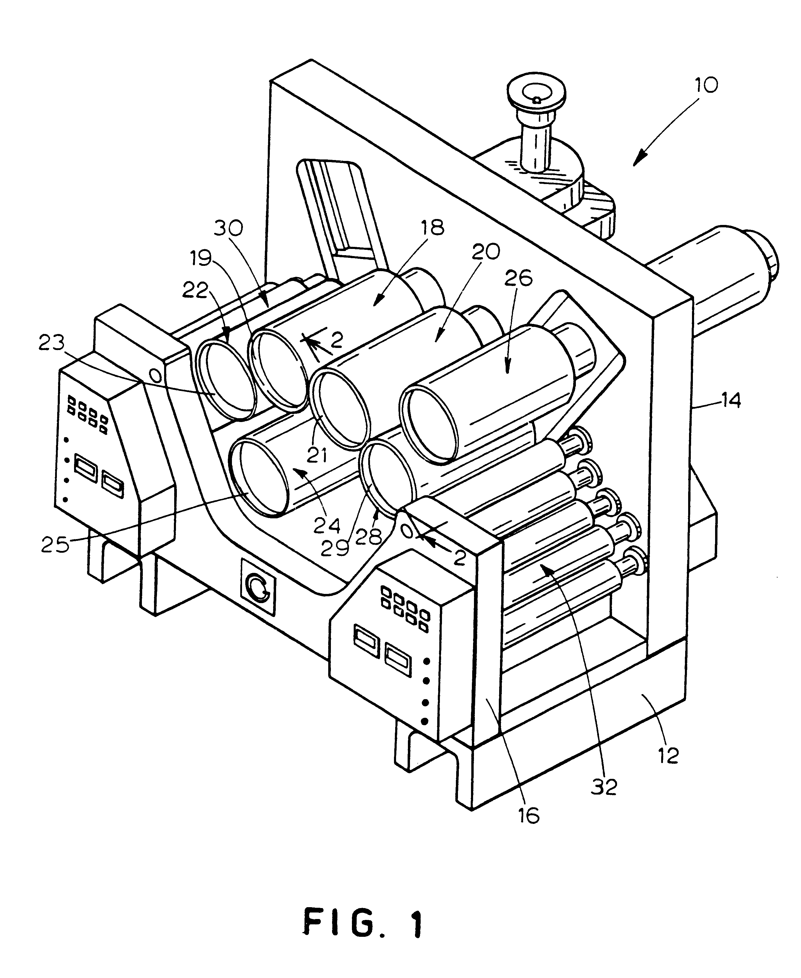
Referring now to the drawings, FIG. 1 illustrates a rotary offset printing press incorporating the features of the present invention and which is generally referred to by the reference numeral 10. Press 10 includes a frame 12 and a pair of opposing side walls 14, 16. Press 10 also includes a pair of blanket cylinder assemblies 18, 20 between which passes a web of paper (not shown) to be printed Each of the blanket cylinder assemblies 18, 20 is disposed adjacent a pair of plate cylinder assemblies 22, 24 and 26, 28, respectively. Blanket cylinder assemblies 18, 20 each support a generally hollow rotatable blanket cylinder 19, 21, respectively, and plate cylinder assemblies 22, 24, ...


PUM


Abstract

A bearing assembly for rotatably supporting the cylinder on a printing press is disclosed. The printing press comprises a frame, a support shaft, a cylinder, and the bearing assembly. The support shaft includes an inner fixed end attached to the frame, a free end disposed outwardly away from the frame, and an interconnecting central portion. The bearing assembly rotatably supports the cylinder on the support shaft The bearing assembly includes an inboard bearing set secured to the support shaft adjacent the central portion, and further includes an outboard bearing set secured to the support shaft adjacent the free end. A portion of the bearing assembly is adapted to permit angular adjustment of the cylinder about an axis perpendicular to the support shaft longitudinal axis.

Description

FIELD OF THE INVENTIONThe present invention relates generally to a rotary offset printing press having removable impression and blanket sleeves mounted on axially rotatable plate and blanket cylinders, respectively. More specifically, the present invention relates to an improved bearing assembly for rotatably supporting such cylinders.BACKGROUND OF THE INVENTIONRotary offset printing presses having rotatable cylinders and removable impression and blanket sleeves are generally well known in the art. Such presses typically operate at very high speeds and are capable of printing a high quantity of material in a relatively short period of time. A continuous web of paper passes between a pair of rotating blanket cylinders which print images on opposites sides of the paper web. Each blanket cylinder is in contact with a plate cylinder having an impression sleeve which has been inked and dampened and which transfers the images to the blanket cylinder for printing onto the web in a manner w...

Claims


Application Information

Patent Timeline
Patent Type & Authority Patents(United States)
IPC IPC(8): B41F13/20B41F13/08B41F30/00B41F7/02B41F13/00B41F13/14B41N10/00
CPCB41F13/14B41F13/20B41P2213/734B41P2217/13B41P2217/15B41P2227/21
Inventor NIEMIRO, THADDIUS A.ORZECHOWSKI, THOMAS W.KULESZA, RADOSLAW
Owner SHANGHAI ELECTRICGROUP CORP
Why Eureka
Try Eureka