Induction-heating fusion device

a fusion device and induction heating technology, applied in the field of fusion devices, can solve the problems of increasing the size of the device, inability to maintain the fusion temperature,

Inactive Publication Date: 2001-11-20
MINOLTA CO LTD
View PDF5 Cites 57 Cited by
  • Summary
  • Abstract
  • Description
  • Claims
  • Application Information

AI Technical Summary

Benefits of technology

Accordingly, it is an object of the present invention to provide an induction-heating fusion device which is capable of stabilizing the fusing temperature over the entire width of a sheet to be passed therethrough by inhibiting an excessive temperature rise in a sheet-nonpassing zone defined, for example, when a small-size sheet passes through the device.
A second object of the present invention is to provide an induction-heating fusion device which is capable of maintaining a fusion-suited temperature over an extent from a central portion to opposite end portions of the device with the use of an induction coil having a coil length substantially equal to the maximum sheet width of usable sheets.

Problems solved by technology

Since this sheet-nonpassing zone fails to allow heat to escape through the sheet, the temperature is elevated markedly, which causes the permeability of the iron core to vary, thus resulting in an unstable fusion temperature.
In addition, such an excessive temperature rise in the nonpassing zone also facilitates deterioration of the device components such as the induction coil and electrically conductive member in that zone.
Thus, the prior art induction-heating device also involves a problem of an increased device size.

Method used


Image

  • Induction-heating fusion device
  • Induction-heating fusion device
  • Induction-heating fusion device

Examples


embodiment 1

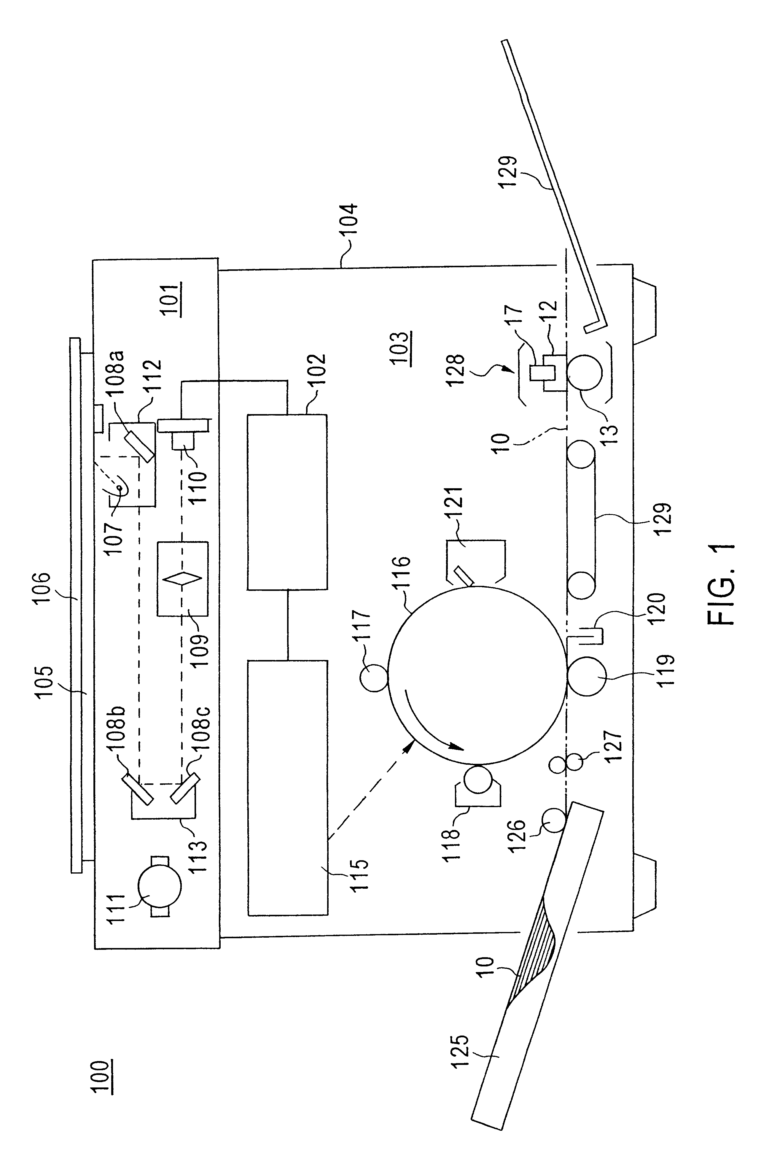
FIG. 1 is a schematic view illustrating a copying machine 100 as an image forming apparatus incorporating an induction-heating fusion device according to the present invention.

As shown, the copying machine 100 includes an image scanner section 101 for scanning an original document, a signal processing section 102 for processing signals, a printer section 103 for outputting to a sheet 10 as a recording medium the print of an image equivalent to the image of the original document resulting from the scanning at the image scanner section 101, and a casing 104 in which these sections are disposed or accommodated.

In the image scanner section 101, the original document placed on a platen glass 105 is pressed by a platen cover 106 which may be replaced with an automatic original document feeder not shown, as the case maybe. The original document on the platen glass 105 is illuminated by a lamp 107, and light reflected by the original document forms an image on a CCD line image sensor 110 th...

embodiment 2

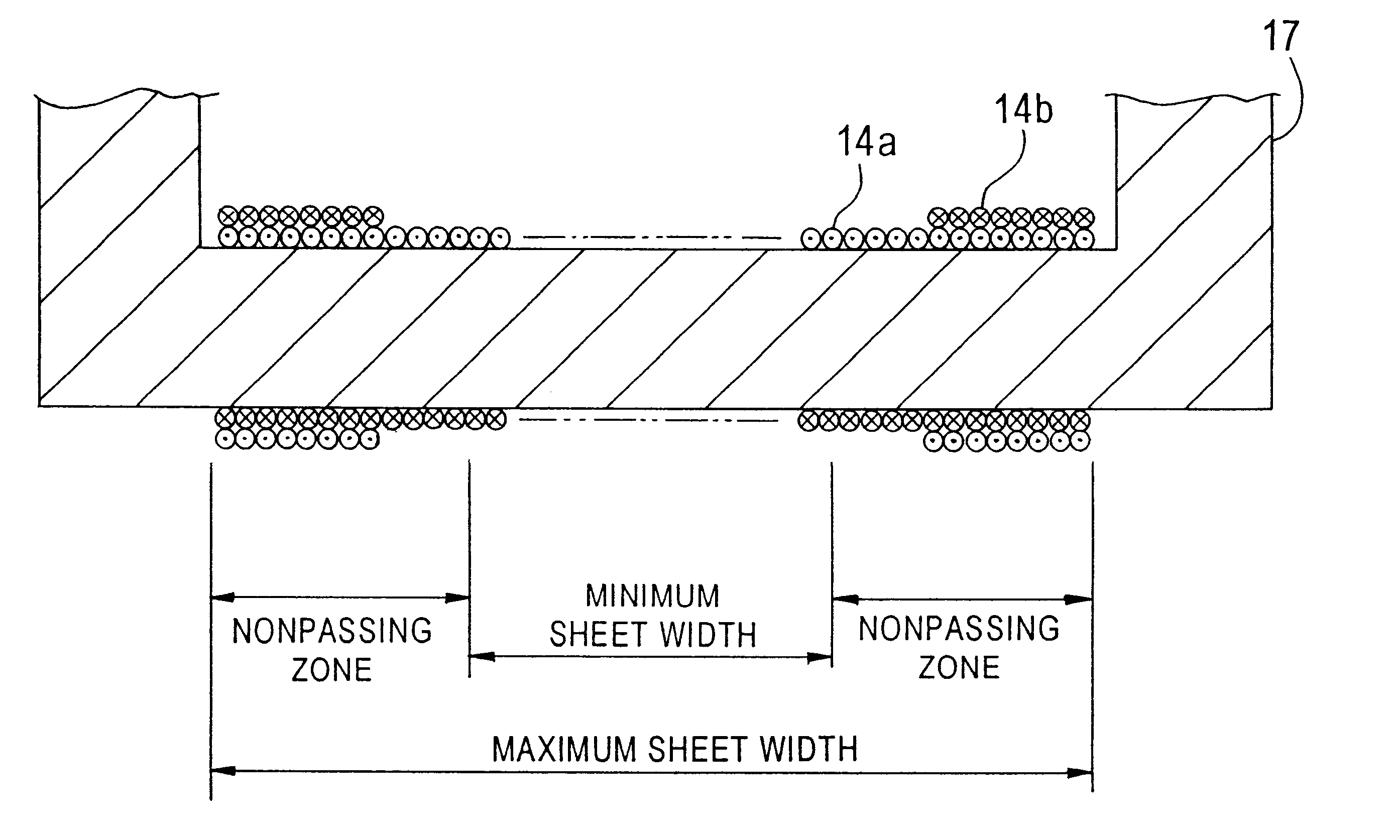
is an arrangement adapted to prevent a temperature decrease in the opposite end portions as seen from the curve (c) by exciting the second induction coil 14b in the same direction as the excited direction of the first induction coil 14a, so that even a sheet of size 1 can be subjected to a temperature ensuring the satisfactory fusion intensity level over the entire width thereof.

Further, as seen from the curve (b), EMBODIMENT 2 is capable of inhibiting an excessive temperature rise in the sheet-nonpassing zone defined in the opposite end portions when a sheet of size 2 is passed by failing to apply current to the second induction coil 14b, because the coil length is shorter than that in the conventional art.

Still further, as seen from the curve (d), EMBODIMENT 2 is capable of minimizing a temperature rise in the opposite end portions including a larger sheet-nonpassing zone defined when a smaller-size sheet, or sheet of size 3 is passed by exciting the second induction coil 14b in a...

embodiment 3

EMBODIMENT 3 further includes a third induction coil (induction sub-coil) . It should be noted that this embodiment is common to EMBODIMENT 1 described above in the overall construction of the copying machine as the image-forming apparatus, that of the fusion device and the like and, hence, the description of such common constructions and features are omitted.

FIG. 8 is a fragmentary sectional view illustrating a coil section according to EMBODIMENT 3.

As shown, this embodiment includes first induction coil 14a having a coil length equal to the maximum sheet width and wound around core 17, second induction coil 14b wound in a direction opposite to the winding direction of the first induction coil 14a and provided in the opposite end portions only, and third induction coil 14c wound in the same direction as the winding direction of the first induction coil 14a and provided only in endmost parts of the opposite end portions.

FIG. 9 illustrates a circuit for supplying power to these coils...


PUM


Abstract

The present invention has an object to provide an induction-heating fusion device which is capable of stabilizing the fusing temperature over the entire width of a sheet therethrough by inhibiting an excessive temperature rise in a sheet-nonpassing zone defined when a small-size sheet is subjected to fusion. The induction-heating fusion device according to the present invention includes an iron core 17 forming a closed magnetic circuit, a main induction coil 14a wound around the iron core 17 for generating a magnetic flux which causes an electrically conductive member to generate an induction current circumferentially thereof, and at least one induction sub-coil 14b provided on an end portion of the main coil for generating a magnetic flux which causes the electrically conductive member to generate an induction current circumferentially thereof.

Description

RELATED APPLICATIONThis application is based on application No. H11-202022 filed in Japan, the entire content of which is hereby incorporated by reference.BACKGROUND OF THE INVENTION1. Field of the InventionThe present invention relates to fusion devices for use in, for example, electrophotographic copying machines, printers and facsimile apparatus, and more particularly, to a fusion device adapted to fuse toner images onto a recording medium by utilizing low-frequency induction heating.2. Description of the Related ArtIn an image forming apparatus such as an electrophotographic copying machine, printer or facsimile apparatus, there is provided a fusion device adapted to fuse toner images onto a recording medium such as a paper sheet or a transfer material carrying the same.Although various types of fusion devices exist, there have been proposed induction-heating type fusion devices which exhibit a higher energy conversion efficiency than fusion devices of the type having a halogen ...

Claims


Application Information

Patent Timeline
Patent Type & Authority Patents(United States)
IPC IPC(8): G03G15/20H05B6/14
CPCG03G15/2053H05B6/145
Inventor KIMATA, AKINORITSUJIMOTO, TAKAHIRO
Owner MINOLTA CO LTD
Why Eureka
Try Eureka