
Lens housing having aperture device

a technology of aperture device and lens housing, which is applied in the direction of mounting, camera body details, instruments, etc., can solve the problems of increased cost, increased occupied space, and complicated configuration

Inactive Publication Date: 2001-11-27
OLYMPUS CORP
View PDF6 Cites 79 Cited by
  • Summary
  • Abstract
  • Description
  • Claims
  • Application Information

AI Technical Summary

Problems solved by technology

This complicates the configuration, thereby providing unavoidable disadvantages such as that costs and the occupied space are forced to increase.

Method used


Image

  • Lens housing having aperture device
  • Lens housing having aperture device
  • Lens housing having aperture device

Examples


first embodiment

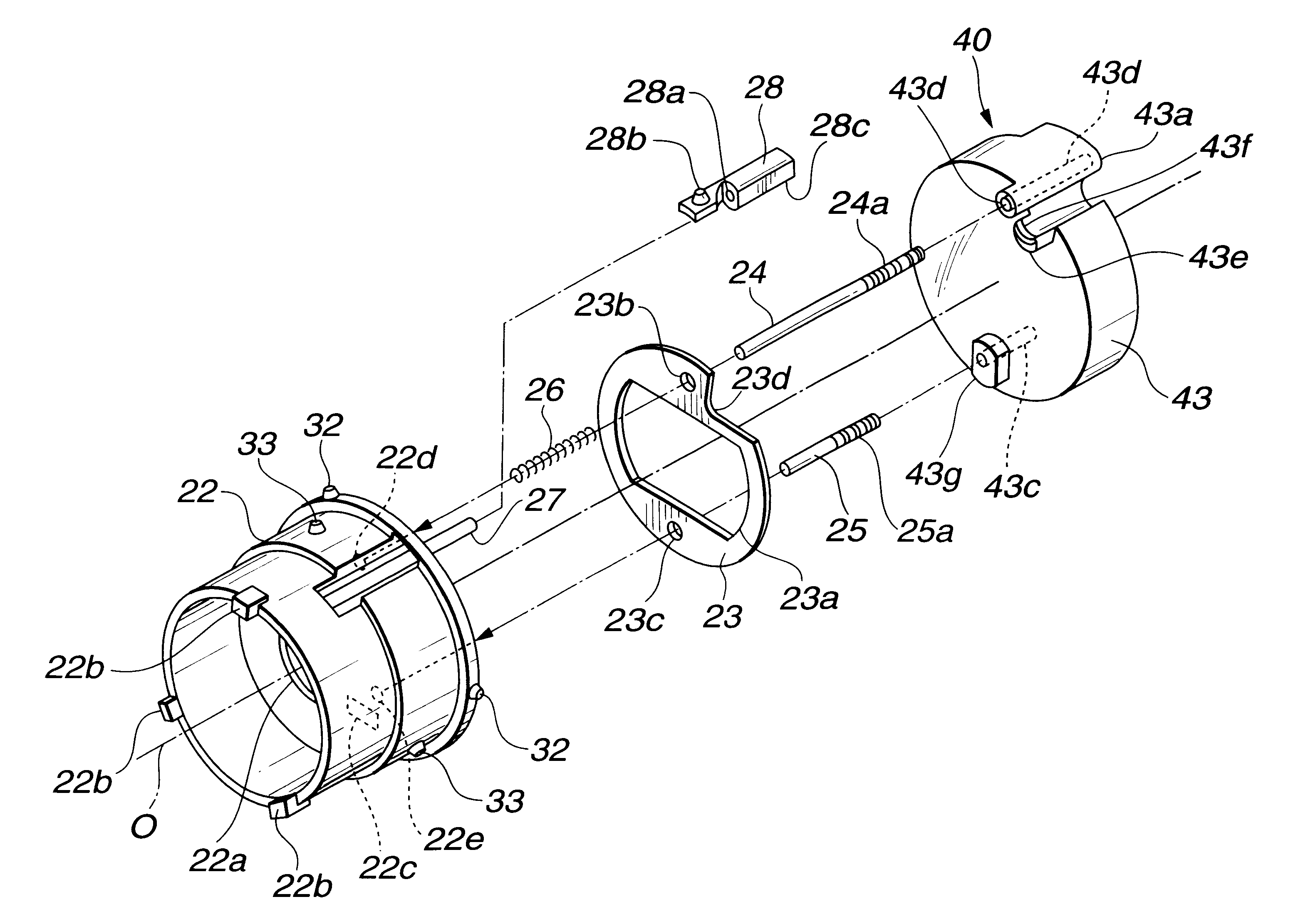
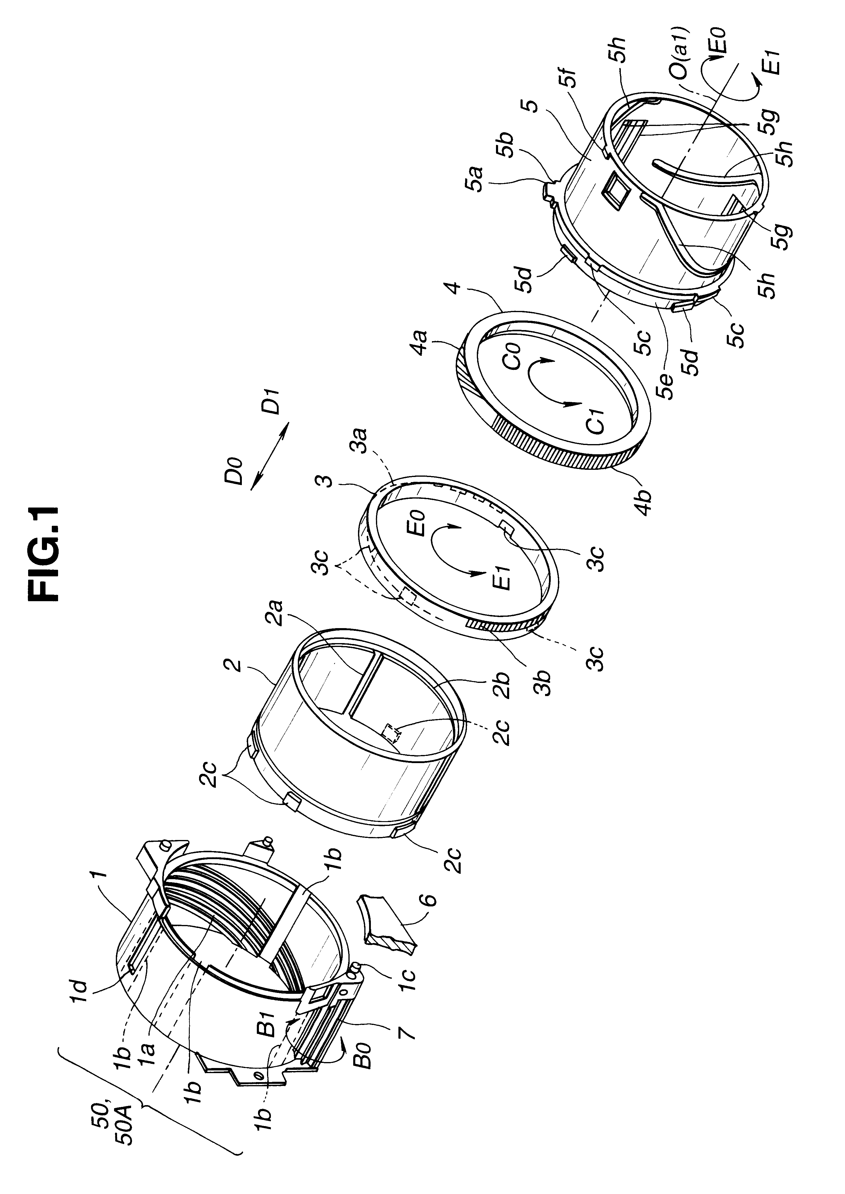
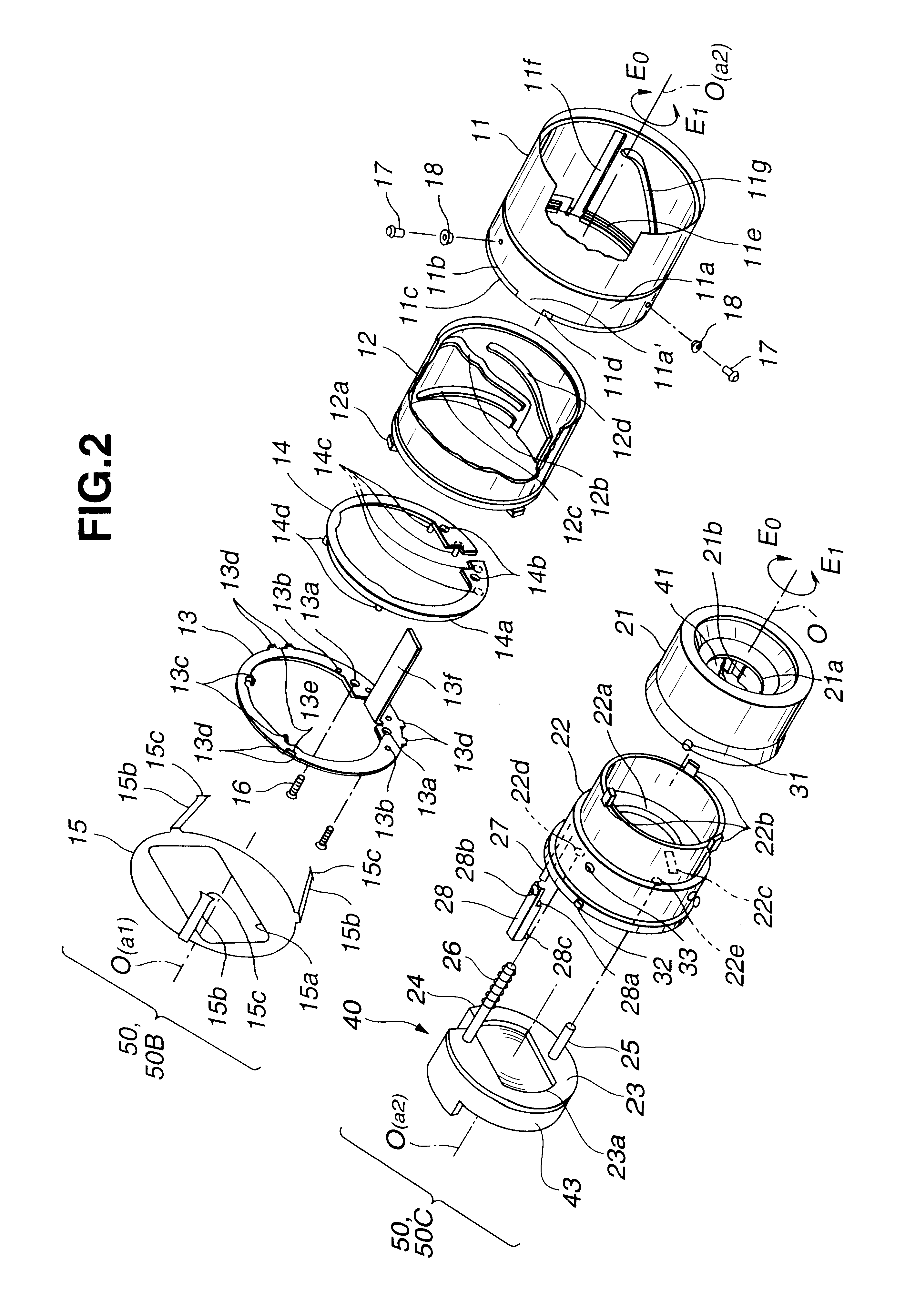
FIGS. 1 and 2 are exploded perspective views of a lens housing 50 including an aperture device according to the present invention. FIG. 3 is a perspective view of a portion where a movable flare aperture 15 is fitted. FIG. 4 is an exploded perspective view of a group-2 frame, an aperture member, and a group-3 frame lens assembly and others. FIGS. 5 and 6 are vertical cross-sectional views of the lens housing 50 in different states; particularly, FIG. 5 is a view of a collapsed-barrel state, and FIG. 6 shows an image-capturing preparation state or a wide-angle state in the upper half portion, and a telescopic state in the lower half. FIG. 7 is a vertical cross-sectional view of a portion where the movable flare aperture 15 is fitted. FIG. 8 is a vertical cross-section view of guide-axis supported state of the group-3 frame lens assembly using a positioner. Referring back to FIGS. 1 and 2, the individual components are not shown in a direction of rotation at the time of assembly in or...

second embodiment

a lens housing including an aperture device according to the present invention is shown in FIG. 9 which is an exploded perspective view of main portions of the lens housing. FIG. 10A is a cross-sectional view along line A--A of FIG. 9. FIG. 10B is a cross-sectional view along line B--B of FIG. 10A.

In this embodiment, the main components are a lens assembly frame 91, and a cam cylinder 98. The moving frame 91 may be an immobilized frame, and includes an axial hole 91a, and an axially extending cutout 91b. A guide pin 93 described below is slidably inserted into hole 91a. A rotation-stopping guide pin 94 described below is slidably inserted into the cutout 91b.

The lens assembly 90 is configured of a lens 92, the guide pin 93, the rotation-stopping guide pin 94, and three cam followers 95, 96, and 97. The lens 92 is preferably formed of an optical-grade plastic.

As an aperture device for restricting incident light, the lens 92 has a shielding-coating applied surface 92b that forms a rec...


PUM


Abstract

A lens housing including an anti-flare aperture device in the form of a thin planar aperture member. In one embodiment, a plurality of guide pins extend from a group-3 lens element, with a compression spring on one of the guide pins to bias the group-3 lens in the direction of its optical axis. The aperture member, the position of which is defined by two guide pins, is sandwiched between the group-3 lens and the compression spring, thereby being supported. The aperture member moves backward and forward together with the group-3 lens supported by the guide pins. In a second embodiment, the aperture device is attached directly to one side of the lens elements.

Description

1. Field of the InventionThe present invention relates to a lens housing having an aperture device; particularly, the invention relates to a structure thereof.2. Description of the Related ArtConventionally, a lens housing having a flare-cutting aperture member for an optical apparatus, such as a camera, has been proposed according to Japanese Unexamined Patent Publication No. 10-010396. In the lens housing, the aperture member is provided in front of a predetermined lens so as to move backward and forward. When a lens other than the predetermined lens is move toward the predetermined lens by the amount exceeding a predetermined amount, the aperture member is driven toward the predetermined lens.In the described lens housing, however, since the aperture member is supported so as to move backward and forward, there must be provided a supporting rod and a lens frame that are dedicated for slidably supporting the aperture member. This complicates the configuration, thereby providing un...

Claims


Application Information

Patent Timeline
IPC IPC(8): G02B27/00G02B7/10G03B17/04G03B9/02
CPCG02B7/102G02B27/0018
Inventor TAKANASHI, TATSUOSATO, MITSUHIRO
Owner OLYMPUS CORP
Learn More