
Memory system for multisignal

Inactive Publication Date: 2001-11-27
FUKUDA HIROSI
View PDF3 Cites 4 Cited by
  • Summary
  • Abstract
  • Description
  • Claims
  • Application Information

AI Technical Summary

Benefits of technology

The low recording cost means high marketability. This invention can be applied to conventional magnetic tapes, disks, and cards as well which are now widely used and will be used more widely in future.
As for the processing speed, this invention doesn't need to move the head so frequently as the binary system does, for this method uses multisignal and each of them out, and correction can be achieved easily.

Problems solved by technology

Today there is no circuit technology for multisignal in multiple notation.
It is true that conventional binary technology and relating microcomputer technology can be applied to multi-notation multisignal too, but the result is far from satisfaction.
For this reason, it has often happened recently that memory capacity really runs short.
But the size of a recording medium(tape, disk, etc.) has its own limit, and so does its recording space.
Though there is a growing need today to record a large quantity of data, recording capacity of media is getting relatively smaller.
Sometimes recording is really impossible because of the shortage of the memory capacity.
Therefore, the conventional recording system can hardly record a large amount of various complicated phenomena of today.
This makes a big problem.

Method used


Image

  • Memory system for multisignal
  • Memory system for multisignal
  • Memory system for multisignal

Examples


Embodiment Construction

This is an explanation of the best embodiment of the invention with actual examples, referring to the drawings.

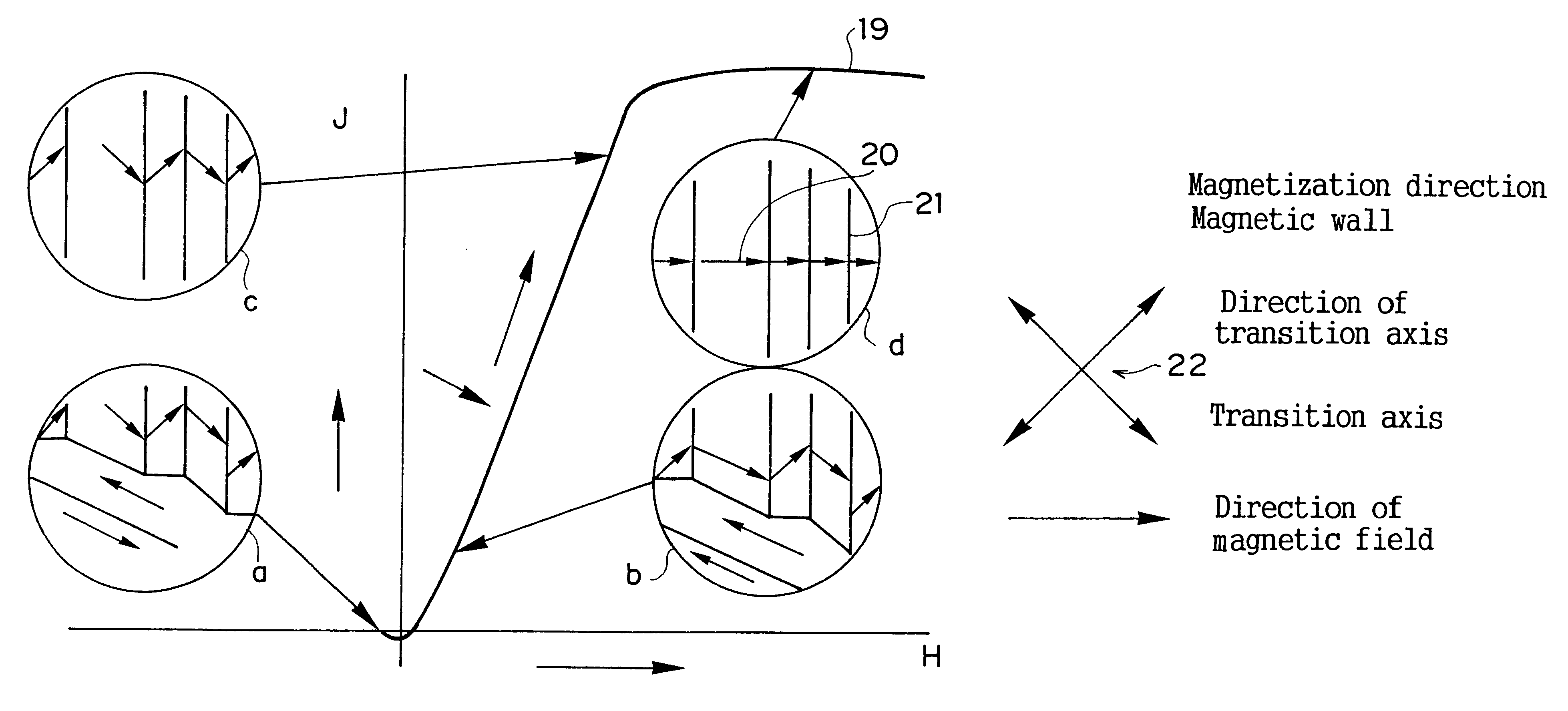
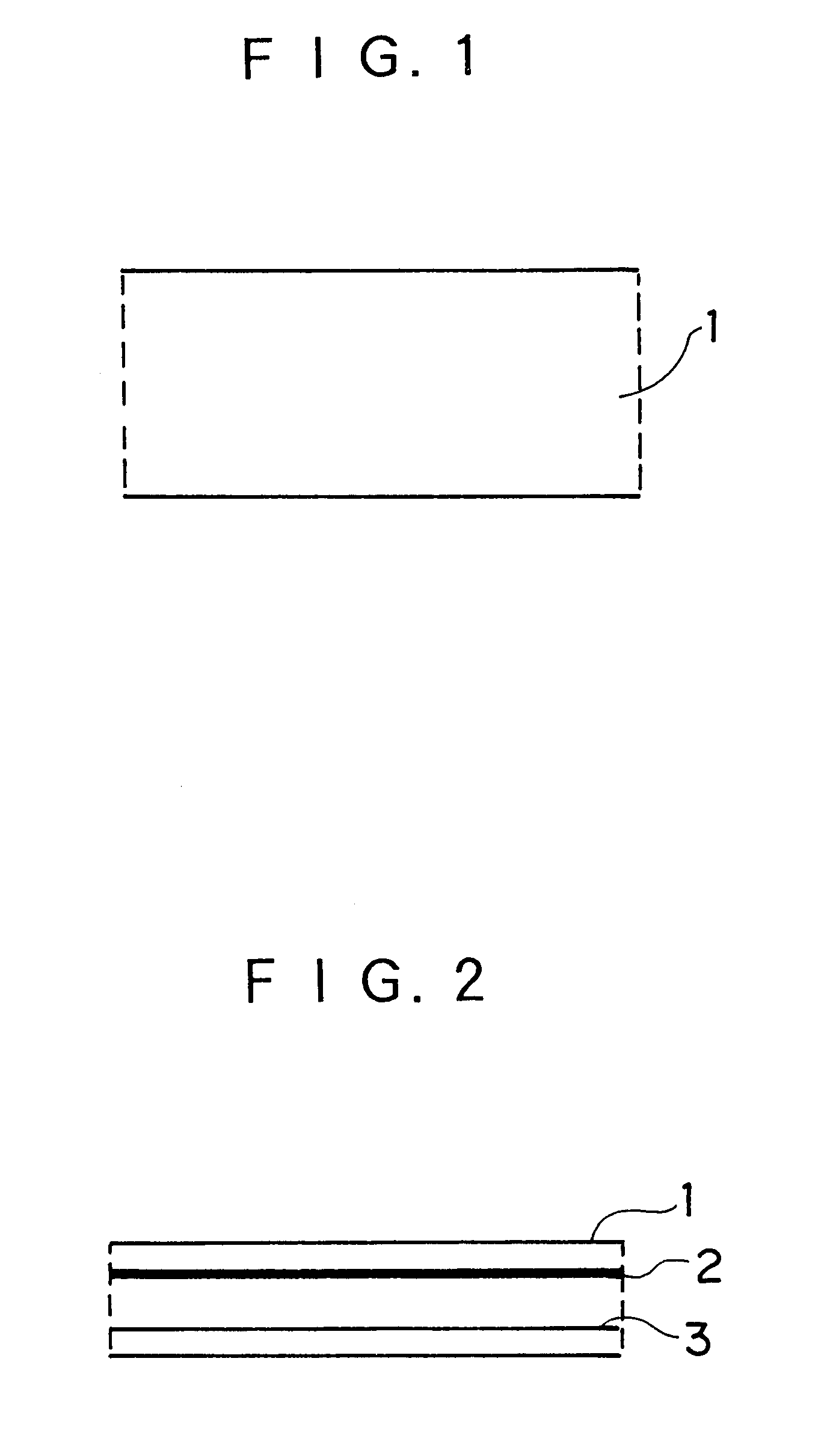
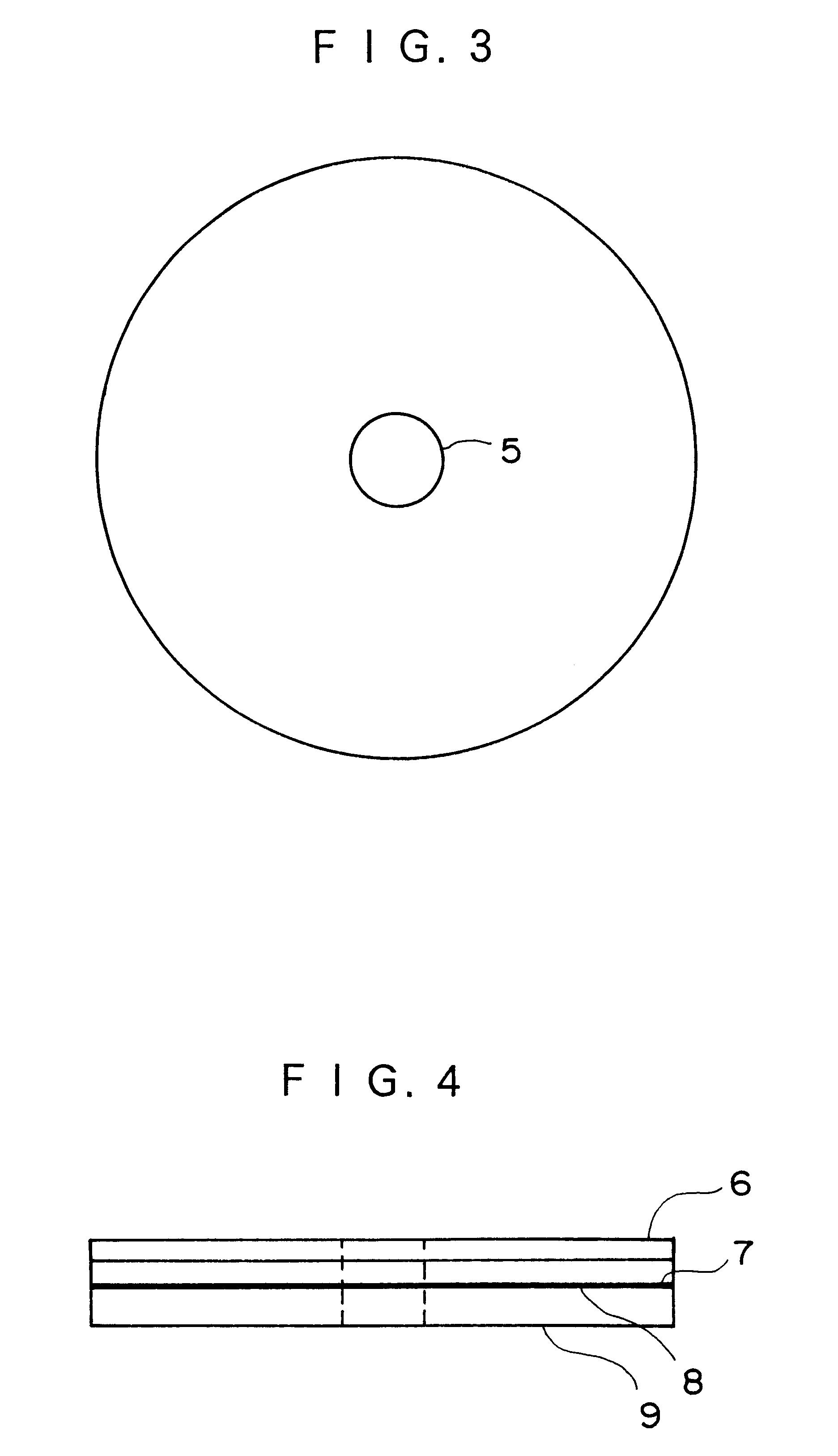
FIG. 1 shows an example of the structure of a magnetic film and a magnetic floppy disk for multisignal. In these media, different kinds of magnetic points can be recorded according to intensity of magnetism.

(a) illustrates the structure of videotape as a plaster-type of flexible medium. (1) is the plan of the tape and (2) is its vertical section.

To a polyester base film 3, an undercoat 2 is given. Then a magnetic layer 1 is formed by plastering such a magnetic substance as .gamma.-Fe.sub.2 O.sub.3, CrO.sub.2 or Co-.gamma.- Fe.sub.2 O.sub.3 with its binder onto the undercoat. On the reverse side, a beck coat 4 made of conductive carbon is applied for the purpose of protection.

(b) shows the structure of a magnetic floppy disk for computers as a thin-film type of hard medium. (1) is the plan of the disk and (2) is its vertical section.

To a base disk 9 of AIMg alloy, a Ni--P un...


PUM


Abstract

Some of various multisignal (a plurality of signals except zero in the conventional binary system ) which are a variety of memories employed as signals instead of a single memory in the binary system are recorded in a medium for multisignal, by moving a recorder for multisignal to a determined position. An extractor is moved to a determined position to extract a part of the multisignal which have been recorded at that position in advance. When any change has to be made to the recorded multisignal, the change is made by the recorder. The multisignal can be used in two or more pairs as well. When processing a signal in the multisignal method in which various signals are used instead of 1 in the conventional binary system, the medium erases, writes, and corrects the signal with a machine which uses multisignal of light, magnetism, etc. that can be clearly discriminated from one another. By this method, the memory size and the speed can be increased and the cost can be lowered, and the memory can be used widely for a personal computer, a word processor, a card, an information equipment, an ATR, a VTR, a D-VTR the Internet, and many other applications.

Description

This application is a 371 of PCT / JP98 / 01213, filed Mar. 20, 1998.1. Technological FieldToday there is no circuit technology for multisignal in multiple notation. It is true that conventional binary technology and relating microcomputer technology can be applied to multi-notation multisignal too, but the result is far from satisfaction.As the binary recording system is on the presence / absence of 1(one), even a small quantity of data requires a large recording space. For this reason, it has often happened recently that memory capacity really runs short.Therefore, the present invention intends to provide a multisignal recording system which enables a larger memory capacity and yet requires a space of almost the same size as required in the conventional system.This invention relates to a method of producing various kinds of memory points to record digital or analog signals, each point expressing a different meaning according to a certain rule.This method has had no comparable one up to ...

Claims


Application Information

Patent Timeline
IPC IPC(8): G11B20/10G11B20/14H04L25/49G11B5/02G11B5/09G11B7/00G11B7/0045
CPCG11B20/10527G11B20/1496H04L25/4917
Inventor FUKUDA, HIROSI
Owner FUKUDA HIROSI
Learn More