Vacuum-cleaner with recirculation of exhaust air

a vacuum cleaner and exhaust air technology, applied in the field of vacuum cleaners, can solve the problems of difficult to simply ensure air tightness, inconvenience, and difficulty in simple cleaning, and achieve the effects of reducing the weight of lead wires, facilitating the layout of lead wires, and shortening the length of lead wires

Inactive Publication Date: 2001-12-04
TOSHIBA TEC KK
View PDF12 Cites 13 Cited by
  • Summary
  • Abstract
  • Description
  • Claims
  • Application Information

AI Technical Summary

Benefits of technology

According to the invention described, a portion of the exhaust air passage extending from the cleaner main body to a handling side operating portion of the pipe body for controlling the electric fan is provided with a lead wire for controlling the electric fan by operation of the handling side operating portion. As a result, since the exhaust air from which dust has been already collected flows in the portion of the exhaust air passage extending from the cleaner main body to the handling side operating portion, it is possible to eliminate an inconvenience that the dust is caught by the leading wire and thereby the exhaust air passage is clogged with the entangled dust or the leading end is disconnected. Further, by extending the lead wire provided in the exhaust air passage nearly in line along the longitudinal direction of the exhaust air passage, it is possible to shorten the length of the lead wire and reduce the weight of the lead wire, and also facilitate the layout of the lead wire and simplify the configuration of the pipe body and hence to reduce the number of manufacturing steps and the manufacturing cost.

Problems solved by technology

Such a structure, however, has a problem.
Since the thickness of each of the end surface portions of the connecting ends of the connecting pipe 8 and the suction port body 9 is small, it is very difficult to simply ensure airtightness, and further the suction port body 7 cannot be replaced by another suction device or cannot be, if it fails, exchanged for a new one.
The vacuum cleaner shown in FIG. 18 has another problem.
The vacuum cleaner shown in FIG. 18 has also an inconvenience.
Accordingly, if the above hose is applied to the vacuum cleaner shown in FIG. 18, there arises a problem that, since the lead wire is spirally wound on the hose, the weight of the hose portion is not reduced and it takes a lot of labor to manufacture the hose.
Further, if the lead wire is provided in the suction air passage 11, there occurs a problem in that the sucked dust is caught by the lead wire and thereby the lead wire may be disconnected or the suction air passage may be clogged with the sucked dust.

Method used


Image

  • Vacuum-cleaner with recirculation of exhaust air
  • Vacuum-cleaner with recirculation of exhaust air
  • Vacuum-cleaner with recirculation of exhaust air

Examples


first embodiment

[First Embodiment]

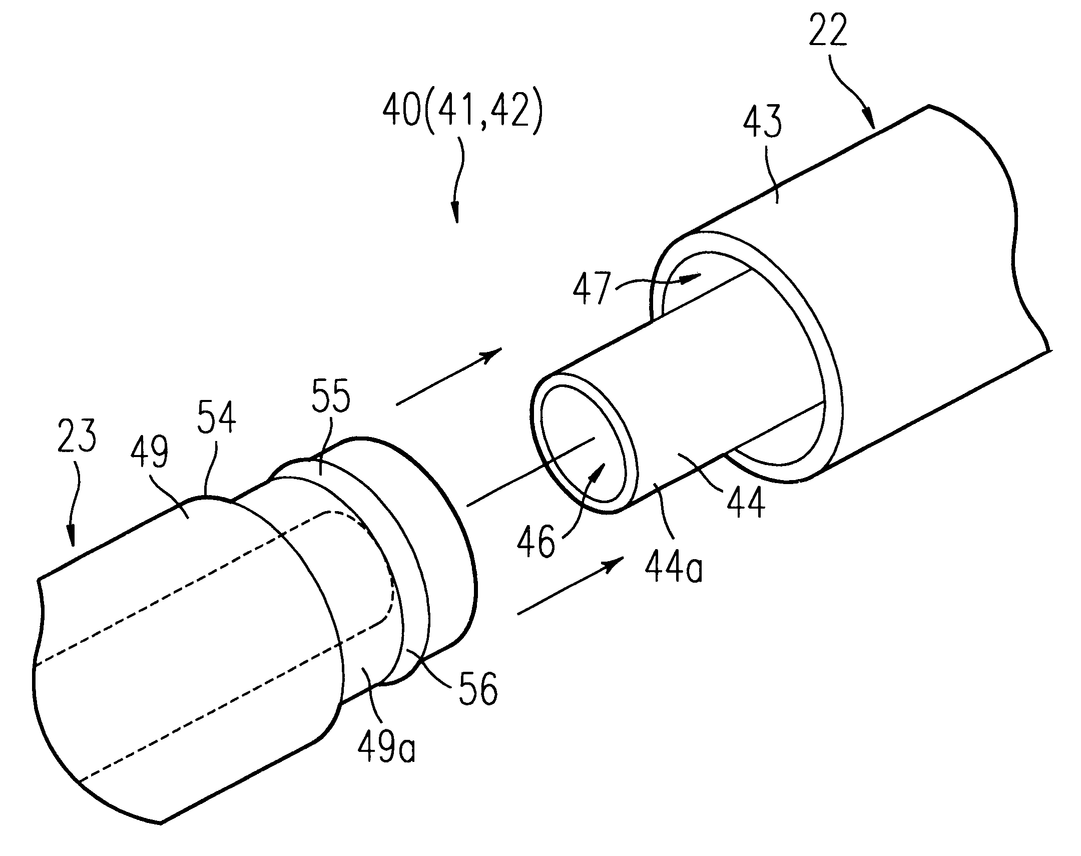
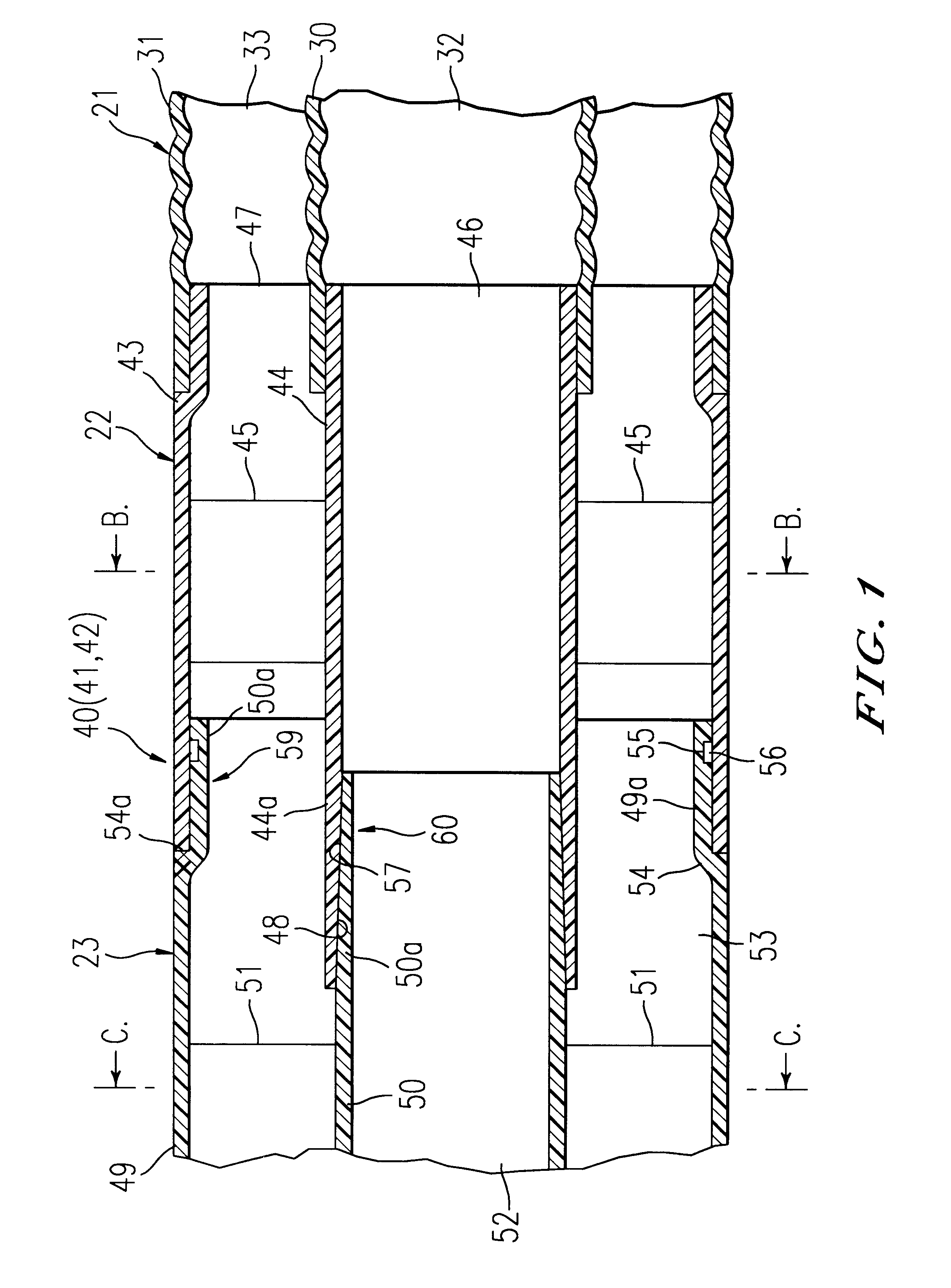
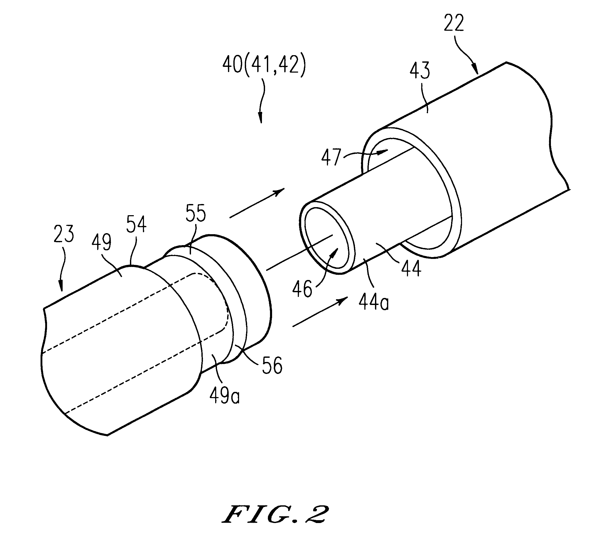
Referring to FIG. 6, a vacuum cleaner has the following elements; a cleaner main body 20; a dust collecting hose (flexible connecting pipe) 21 connected to the cleaner main body 20; a handling side connecting pipe (handling side pipe) 22 fixed at a leading end portion of the dust collecting hose 21; connecting pipes for extension (extension pipes) 23 and 23' connected in series to the handling side connecting pipe 22; and a suction port body 24 connected to the handling side connecting pipe 22 via the extension connecting pipes 23 and 23'.

As shown in FIG. 7, a dust collecting chamber 25 is formed in a front portion of the cleaner main body 20, and a fan chamber 26 is formed in a rear portion of the dust collecting chamber 25. A paper pack filter 27 is disposed as a dust collecting filter in the dust collecting chamber 25, and an electric fan 28 with its suction side 28a communicated to the dust collecting chamber 25 is disposed in the fan chamber 26. An exhaust por...

second embodiment

[Second Embodiment]

Referring to FIGS. 8 and 9, there is a cleaner main body 120 of a vacuum cleaner; a dust collecting chamber 121 formed in a front portion of the cleaner main body 120; a lid body (dust collecting chamber opening / closing lid) 122 for opening / closing the dust collecting chamber 121; a hose connecting port 123 formed in the lid body 122; and a paper pack filter (dust collecting filter) 124 disposed in the dust collecting chamber 121.

A fan chamber 125 is formed in a rear portion of the cleaner main body 120, and an electric fan 126 is disposed in the fan chamber 125. A suction port (suction side) 126a of the electric fan 126 is communicated to the dust collecting chamber 121. The rear portion of the fan chamber 125 is taken as an exhaust chamber 127 separated trout the dust collecting chamber 121, and an exhaust port (exhaust side) 126b of the electric fan 126 is opened in the exhaust chamber 127. An exhaust passage (exhaust air passage) 128 communicated to the exhaus...

third embodiment

[Third Embodiment]

A hose 230 shown in FIGS. 15 to 17 has a dual structure in which a suction hose 234 is mounted in an exhaust hose 233. When the hose 230 in FIG. 17 is connected to a connecting port 225 of the cleaner main body 20, the suction hose 234 in FIG. 15 is communicated to the dust collecting chamber 25 in FIG. 16 and the exhaust hose 233 is communicated to the exhaust chamber 26b.

A space between the exhaust hose 233 and the suction hose 234 is taken in FIG. 15 as an exhaust air passage 233A, and the interior of the suction hose 234 is taken as a suction air passage 234A. A lead wire L extending from the cleaner main body 20 in FIG. 16 to a handling side operating pipe 222 is laid out in FIG. 15 in the exhaust air passage 233A. A conductive terminal (not shown) connected to a conductive socket (not shown) of the connecting port 225 in FIG. 17 is connected to an end portion, on the cleaner main body 20 side, of the lead wire L in FIG. 15. An end portion, on the handling sid...


PUM


Abstract

In a vacuum cleaner, a suction side of an electric fan contained in a cleaner main body is connected to a suction port body via a suction air passage and an exhaust side of the electric fan is connected to the suction port body via an exhaust air passage. Air, passage connecting portions for removably connecting the suction port body to the cleaner main body are provided between both air passages.

Description

BACKGROUND OF THE INVENTION1. Field of the InventionThe present invention relates to a vacuum cleaner in which exhaust air is not discharged out of a cleaner main body but is returned into a suction port body to be recirculated.2. Discussion of the Related ArtAs the vacuum cleaner of this type, for example, one shown in FIG. 18 has been disclosed (see Japanese Utility Model Publication No. 39-36553).Referring to FIG. 18, a vacuum cleaner includes a cleaner main body 1; a filter 2 disposed in the cleaner main body 1; a dust collecting chamber 3 formed in the filter 2; an electric fan 4 disposed in the cleaner main body 1 in such a manner that the suction side thereof is communicated to the dust collecting chamber 3; a suction side connecting port 5 provided in the cleaner main body 1 in such a manner as to be communicated to the dust collecting chamber 3; an exhaust side connecting port 6 provided in the cleaner main body 1 in such a manner as to be communicated to the exhaust side o...

Claims


Application Information

Patent Timeline
Patent Type & Authority Patents(United States)
IPC IPC(8): A47L9/02A47L9/08A47L5/14A47L9/24A47L5/12
CPCA47L5/14A47L9/08A47L9/24
Inventor TAKEMOTO, RITUO
Owner TOSHIBA TEC KK
Why Eureka
Try Eureka