
Choke valve

a choke valve and valve body technology, applied in the field of choke valves, can solve the problems of non-linear setting characteristic of spherical choke bodies, difficult to find reproducible settings, and slight pendulum movement of choke cones

Inactive Publication Date: 2001-12-04
FESTO AG & CO KG
View PDF12 Cites 32 Cited by
  • Summary
  • Abstract
  • Description
  • Claims
  • Application Information

AI Technical Summary

Benefits of technology

One object of the invention is to provide a choke valve of the type initially mentioned with which leads to a linear characteristic and makes possible extremely exact, reproducible settings.
The part of the choke body responsible for the aperture made available is now no longer spherical in form but constituted by a cylindrical choke piston constantly plunging into an inlet flow duct communicating with the inlet. The seal area present between the choke piston and the inlet flow duct wall then prevents pressure medium supplied through the inlet flow duct flowing past the choke piston. Consequently it is only possible for the pressure medium to flow away via the transfer openings, provided in the inlet flow duct wall upstream from the seal area toward the upstream section of the inlet flow duct. Dependent on the particular setting of the choke the total aperture-defining cross section of the transfer openings communicating with the upstream section of the inlet duct, may be preset to varied amounts. By a suitable selection of the design and arrangement of the transfer openings it is then possible to produce a linear setting characteristic in an extremely simple manner. Since, unlike the case of the prior art, the aperture is not in essential respects preset by the annular gap surrounding the choke body, furthermore any irregularities in the axial position of the choke piston are not disadvantageous. Moreover owing to the seal area it is possible to prevent significant leakage past the choke piston so that so that any danger of a pendulum movement is prevented at the outset. In this respect owing to the cooperation of the choke body and the inlet flow duct wall at the seal area it is also possible to achieve a guiding effect having a favorable effect on the positional stability of the choke body.
The wall of the inlet flow duct may readily be an integral part of the valve housing of the choke valve. However, it is particularly convenient to fashion the inlet flow duct wall as a component of a valve cartridge, which may be fitted in any suitably adapted housing provided with an inlet and an outlet. This renders possible extremely simple integration of the choke valve in the housing of any fluid power equipment, for instance fluid power drives.
The choke body may be fixed in position by means of a screw thread so that it is turned for changing the setting of the choke, this simultaneously resulting in a shift in the axial position. However as a more advantageous design a structure actuating means is proposed in which the rotary actuating member is arranged to be rotatable and is simultaneously locked axially, whereas the choke body is prevented from rotating and is able to be moved axially, there being a threaded engagement between the rotary actuating member and the choke body. Turning of the rotary actuating member results in this case in a purely translatory movement of the choke body, the axial position of the rotary actuating member remaining unchanged. This means that, irrespectively of the setting made, there are extremely compact dimensions. Furthermore such a structure makes it easier to adopt features, which render possible a digital setting characteristic of the choke valve. Thus detent means can be provided for detachable attachment of the rotary actuating member in different angular positions, the selection grid pitch bearing a direct linear relation to the aperture set by the choke piston.
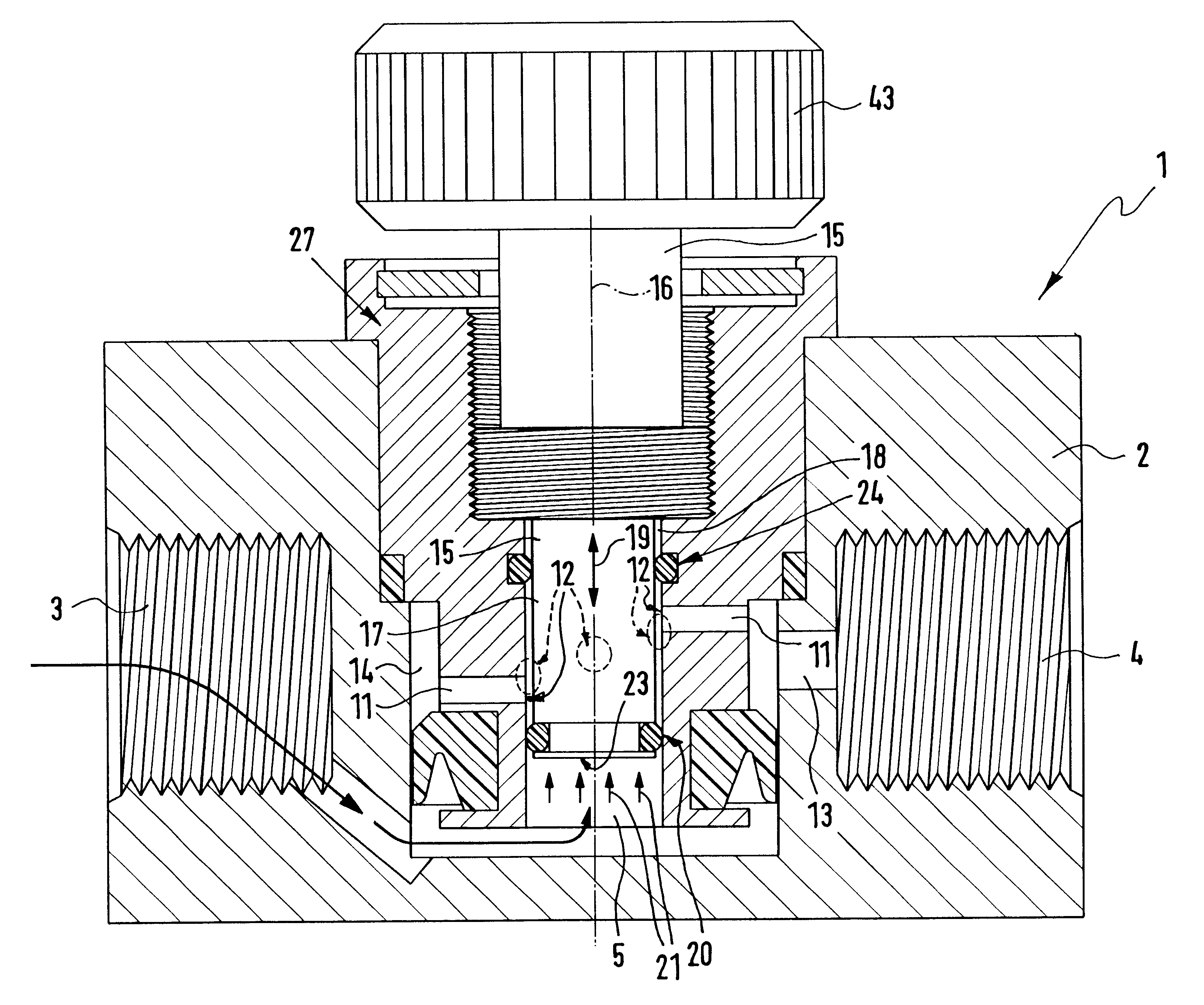
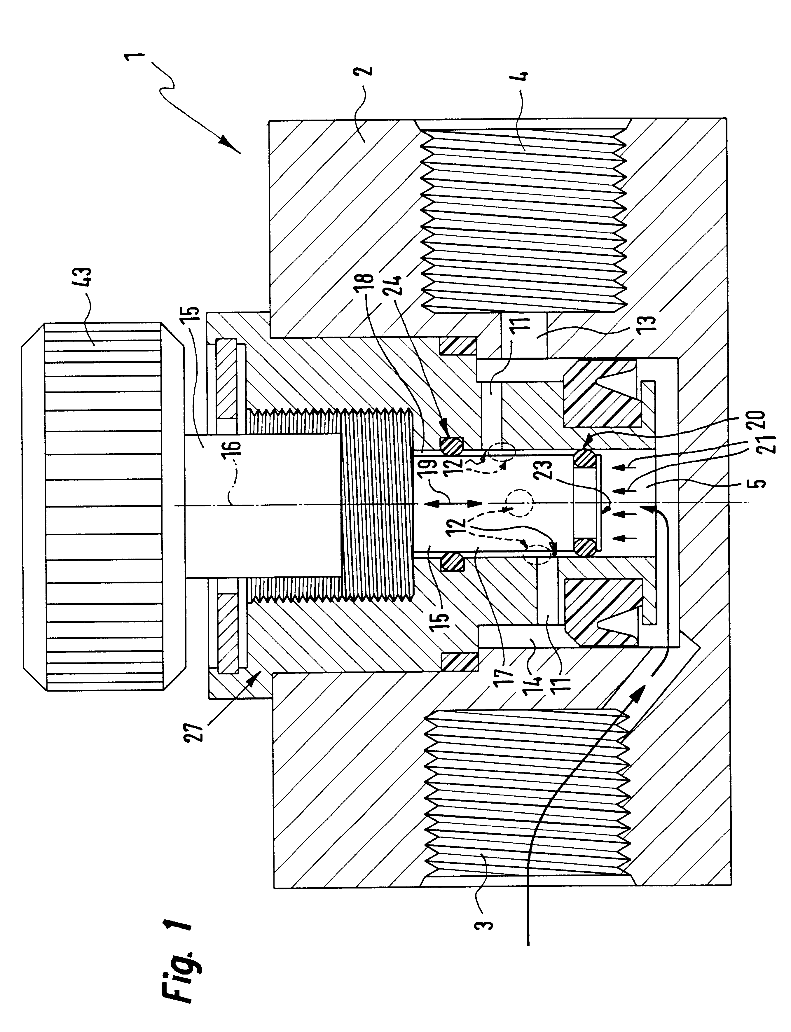
FIG. 1 shows a first design of the choke valve in accordance with the invention in a longitudinal section, the choke piston being in a closed position, which completely prevents flow of the pressure medium from the inlet to the outlet.

Problems solved by technology

A substantial disadvantage of such spherical choke bodies is the non-linear setting characteristic.
The aperture as a rule varies in a square law function in relation to the change of the axial position of the choke body so that it is extremely hard to find reproducible settings.
A further disadvantage is that thread play between the choke body and the valve housing leads to slight pendulum movements of the choke cone on resetting the choke.
This in turn leads to irregular variations in the aperture and to a still further impairment of setting operations.

Method used


Image

  • Choke valve
  • Choke valve
  • Choke valve

Examples


Embodiment Construction

.

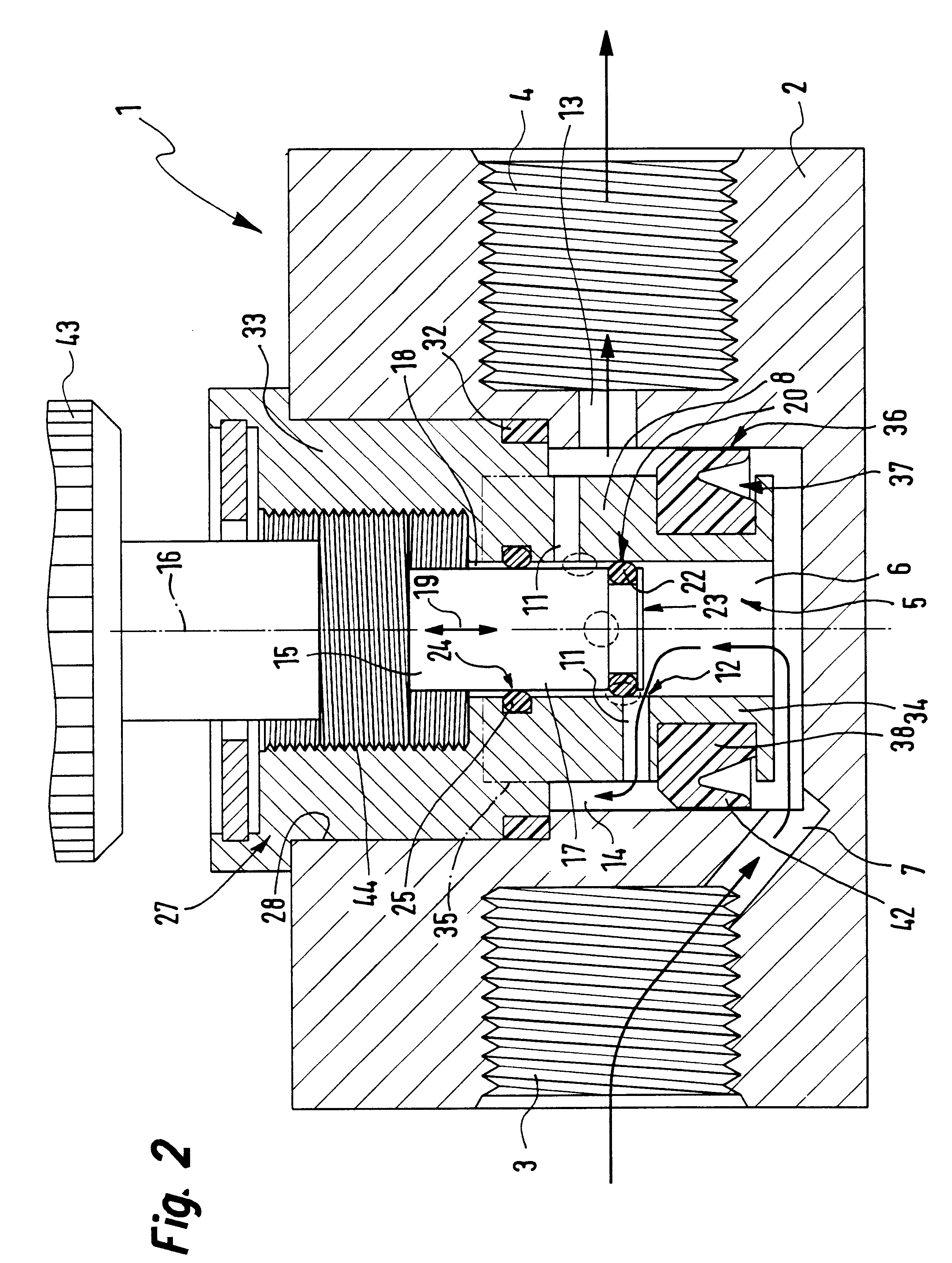
All choke valves 1 illustrated comprise a housing 2 with an inlet 3 and an outlet 4 for a fluid pressure medium, more especially compressed air. The inlet 3 and the outlet 4 are provided with means for the connection of fluid ducts leading to other equipment, such means here being internal screw threads.

In the interior of the housing 2 a linear inlet flow duct 5 is located of circularly cylindrical cross section. Its one axial end portion, in the following referred to as the upstream duct section 6 is in constant communication with the inlet 3 via at least one first fluid duct 7.

The inlet flow duct wall 8 peripherally delimiting the inlet duct 5 has several radially continuous outlet flow ducts 11 extending through it. These outlet flow ducts 11 for their part open on the one hand at apertures 12 peripherally in the inlet flow duct 5. On the other hand they are connected via at least one second fluid duct 13 with the outlet 4.

The choke valve 1 furthermore possesses an elongated cho...


PUM


Abstract

A choke valve, whose choke body comprises a cylindrical choke position plunging coaxially into an inlet duct. The inlet flow duct is connected on the one hand with an inlet and on the other hand communicates through transfer openings with outlet flow ducts extending through the wall of the flow duct, such outlet flow ducts begin connected with the outlet. Between the choke piston and the inlet flow duct wall a seal area is provided, which on resetting the choke body is shifted axially and, cooperating with the transfer apertures, sets the aperture for the pressure medium.

Description

The invention relates to a choke valve comprising a choke body able to be set in the direction of its longitudinal axis and which in a manner dependent on its position (choking position) between an inlet and an outlet makes available a smaller or larger flow aperture.THE PRIOR ARTKnown choke valves of this type, as described for instance in the textbook "Einfuhurng in die Pneumatik", Meixner / Kobler, page 132, possess a spherical choke body, which in manner dependent on the choke setting plunges to a greater or less extent into an opening and so makes available varying apertures for the respective fluid medium. The choke body is rotatably mounted on the valve housing by means of a screw thread and its axial position or, respectively, choke setting may be varied by rotation.A substantial disadvantage of such spherical choke bodies is the non-linear setting characteristic. The aperture as a rule varies in a square law function in relation to the change of the axial position of the chok...

Claims


Application Information

Patent Timeline
IPC IPC(8): F16K47/08F16K47/00F16K1/32F16K1/52F16K15/18
CPCF16K1/52F16K47/08Y10T137/86734Y10T137/86759
Inventor STOLL, KURTKEES, ULRICH
Owner FESTO AG & CO KG
Learn More