Cylinder head gasket

a gasket and cylinder head technology, applied in the direction of engine sealing, machine/engine sealing, etc., can solve the problems of gas through, excessive pressure, and large difference in the amount of projection above the surface of the cylinder block from liner to liner

Inactive Publication Date: 2001-12-11
TAIHO INDUSTRIES CO LTD +1
View PDF13 Cites 37 Cited by
  • Summary
  • Abstract
  • Description
  • Claims
  • Application Information

AI Technical Summary

Benefits of technology

FIG. 5 is an enlarged section illustrating a plastic deformation of an increa

Problems solved by technology

For a multi-cylinder engine including a plurality of press fit liners, if each liner is mounted on the cylinder block in an even manner, there often results a delicate difference in the amount of projection above the surface of the cylinder block from liner to liner.
Accordingly, when the cylinder head gasket is interposed between the cylinder head and the cylinder block, which are then clamped together by clamping bolts, a failure of a bead on the cylinder head gasket may occur in a region thereof which is contacted by a liner which projects above the surface of the cylinder block to cause an excessively high pressure of contact or the offset step on the cylinder block, which is abutted by the liner flange, may be deformed to cause a blow-thr

Method used


Image

  • Cylinder head gasket
  • Cylinder head gasket
  • Cylinder head gasket

Examples


second embodiment

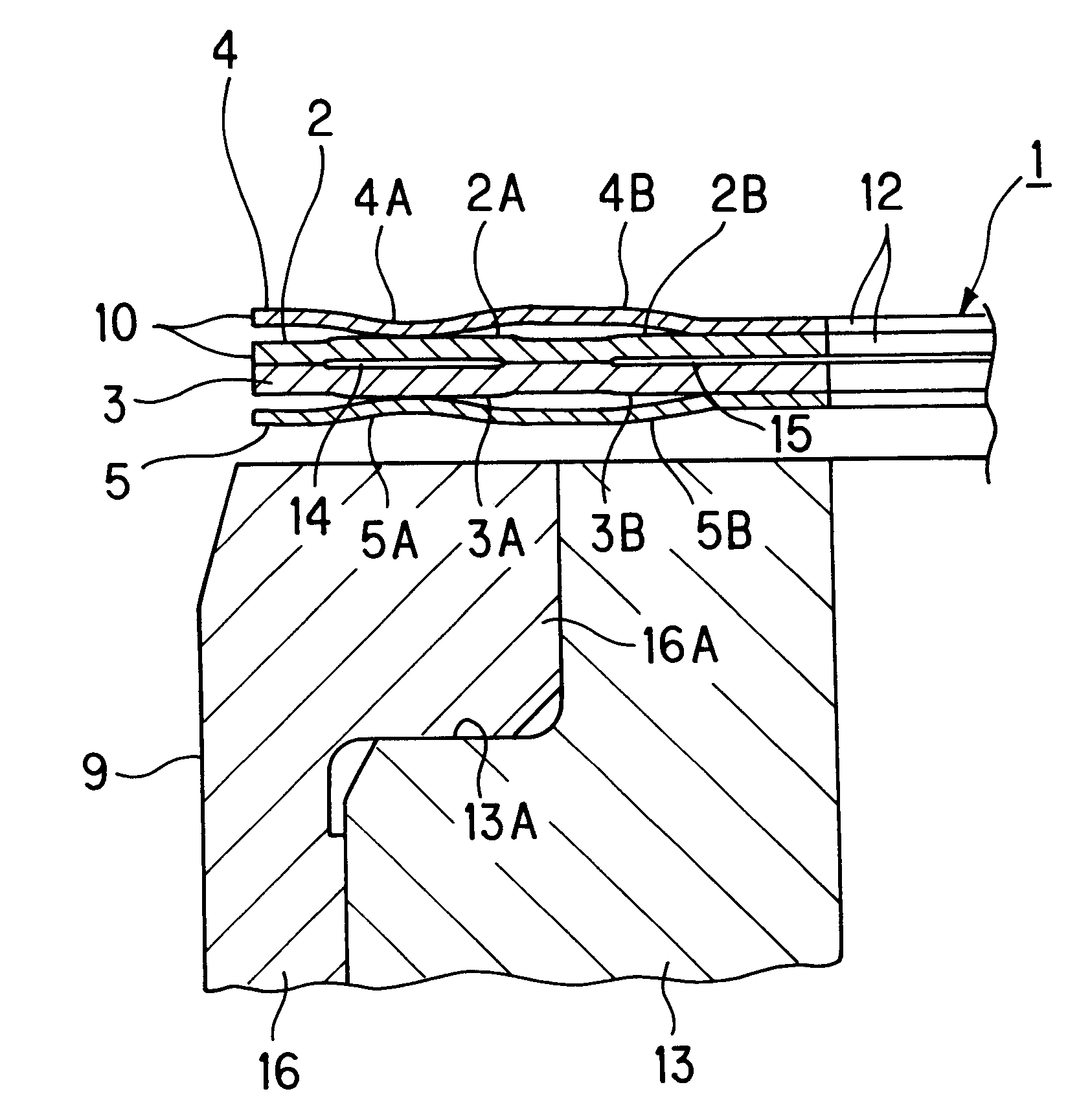
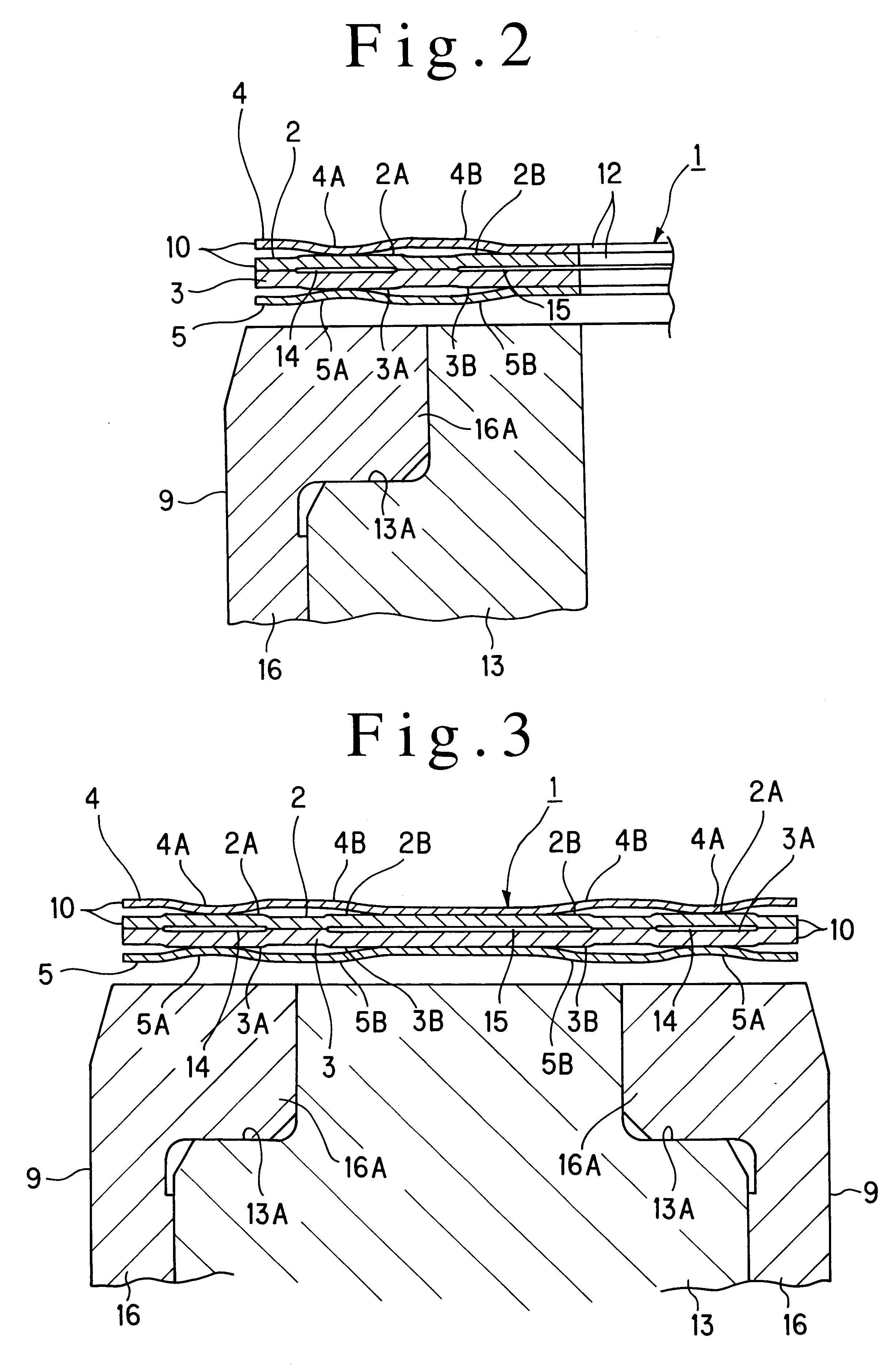
FIG. 7 shows the invention in which the inner projections 2A, 3A are left free without placing them in close contact toward the combustion chamber opening 10 while the outer projections 2B, 3B are formed with sidewalls on both the inner and the outer periphery so that the outer projections are disposed in close contact with each other on the outside of the both sidewalls.

first embodiment

In addition, the full beads 4A, 5A and the half beads 4B, 5B are interchanged in position as compared with the first embodiment, with the half beads 4B, 5B being disposed in overlapping relationship with the corresponding inner projections 2A, 3A and the full beads 4A, 5A being disposed in overlapping relationship with the outer projections 2B, 3B.

It is also to be noted that the full beads 4A, 5A and the outer projections 2B, 3B are disposed nearer the combustion chamber opening 10 than in the first embodiment, whereby the inner periphery of the outer projections 2B, 3B is disposed in overlapping relationship with the liner 16 and the full beads 4A, 5A are disposed across the liner 16 and the cylinder block 13.

FIG. 8 shows a third embodiment of the invention in which the first outer projection 2B of the first gasket substrate 3, the second outer projection 3B of the second gasket substrate 3, the first half bead 4B of the first plate 4 and second half bead 5B of the second plate 5 s...


PUM


Abstract

A cylinder head gasket includes a pair of first and second gasket substrates. The gasket substrates are each formed with a first and a second projection which project in opposite directions, with a clearance therebetween. According to a first aspect of the invention, each projection undergoes a plastic deformation toward the clearance defined between them when the gasket substrates are held sandwiched between a cylinder head and a cylinder block, each projection undergoing a magnitude of plastic deformation which is greater or lesser in accordance with the magnitude of a surface pressure therebetween. According to a second aspect of the invention, each projection is formed with a radially central part which projects toward the radially central part of the other projection and which is in close contact with each other continuously in the circumferential direction.

Description

The present invention relates to a cylinder head gasket used in an engine.DESCRIPTION OF THE PRIOR ARTA cylinder head gasket is known in the art which comprises a first and a second gasket plate disposed in overlapping relationship, held sandwiched between a cylinder head and a cylinder block and each having a combustion chamber opening formed therein in alignment with a cylinder bore.In a cylinder head gasket of the type described, as an explosion pressure of an engine increases, a gas in a combustion chamber may blow through a clearance between the cylinder head gasket and the cylinder head, between the cylinder head gasket and the cylinder block or between a first and a second gasket substrate which form together the cylinder head gasket.For purposes of reducing the weight of an engine, a cylinder block which is made from aluminum has recently been employed, with a cast iron liner being usually provided on the cylinder bore in order to secure an abrasion resistance thereof. Such ...

Claims


Application Information

Patent Timeline
IPC IPC(8): F16J15/08F02F11/00
CPCF16J15/0825F16J2015/085F16J2015/0856F16J2015/0875
Inventor JINNO, OSAMUGOTO, EISABUROOMURA, SEIJIKAWAKITA, TATSUYANAKAMURA, HIDEO
Owner TAIHO INDUSTRIES CO LTD
Why Eureka
Try Eureka