Vertical feed mixer with auger having center post with sloped top

a vertical feed mixer and center post technology, applied in the field of vertical feed mixers, can solve the problems of large reduction of mixer efficiency, danger or unsafe,

Inactive Publication Date: 2001-12-11
JAY LOR INT INC
View PDF17 Cites 43 Cited by
  • Summary
  • Abstract
  • Description
  • Claims
  • Application Information

AI Technical Summary

Problems solved by technology

The time involved obviously varies with the positioning of the bale, but the wrong bale positioning can lead to serious problems.
For example, the operator of the mixer might physically attempt to dislodge the blockage and that can be dangerous or unsafe.
Also, the efficiency of the mixer is greatly reduced when this type of blockage occurs.

Method used


Image

  • Vertical feed mixer with auger having center post with sloped top
  • Vertical feed mixer with auger having center post with sloped top
  • Vertical feed mixer with auger having center post with sloped top

Examples


Embodiment Construction

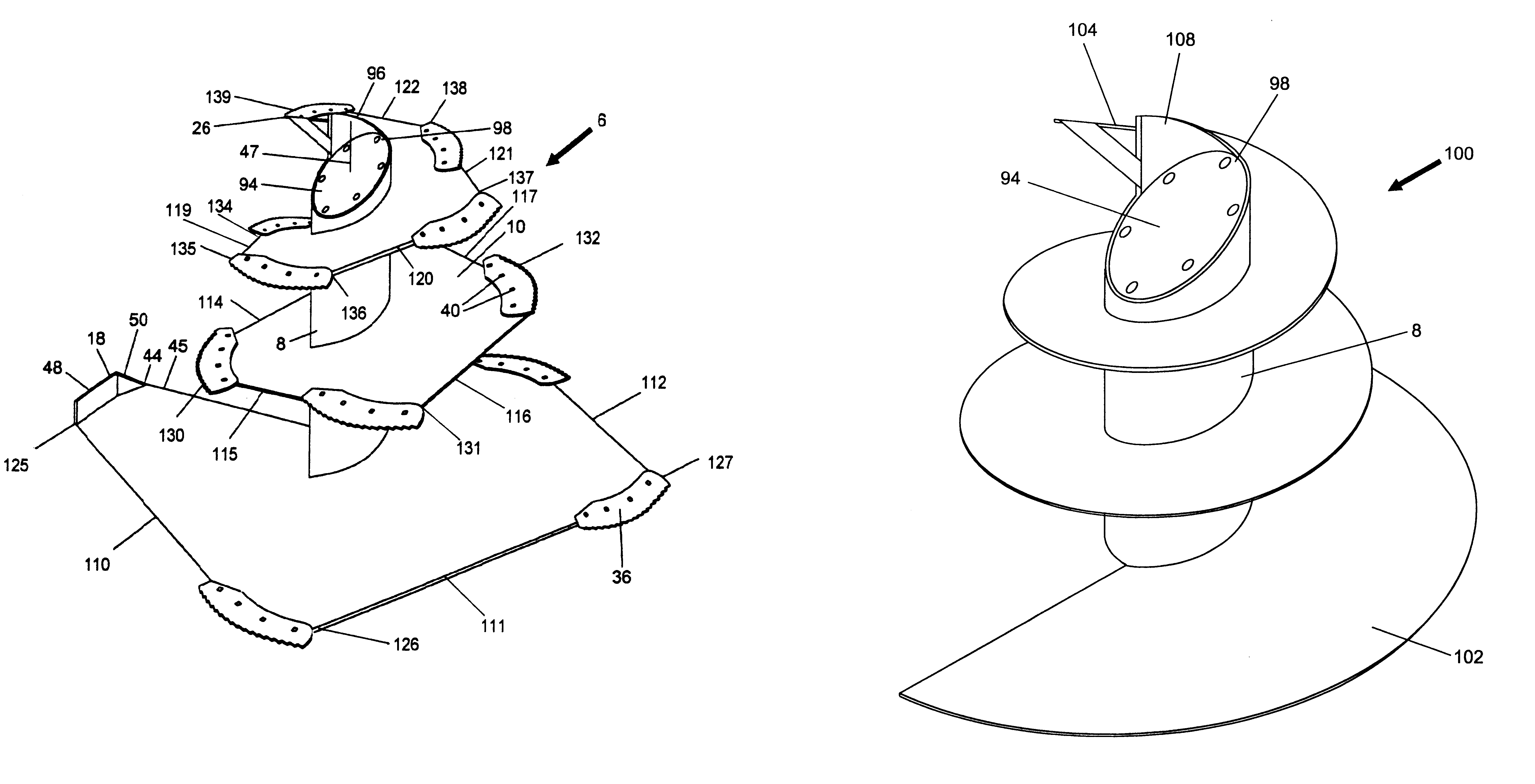
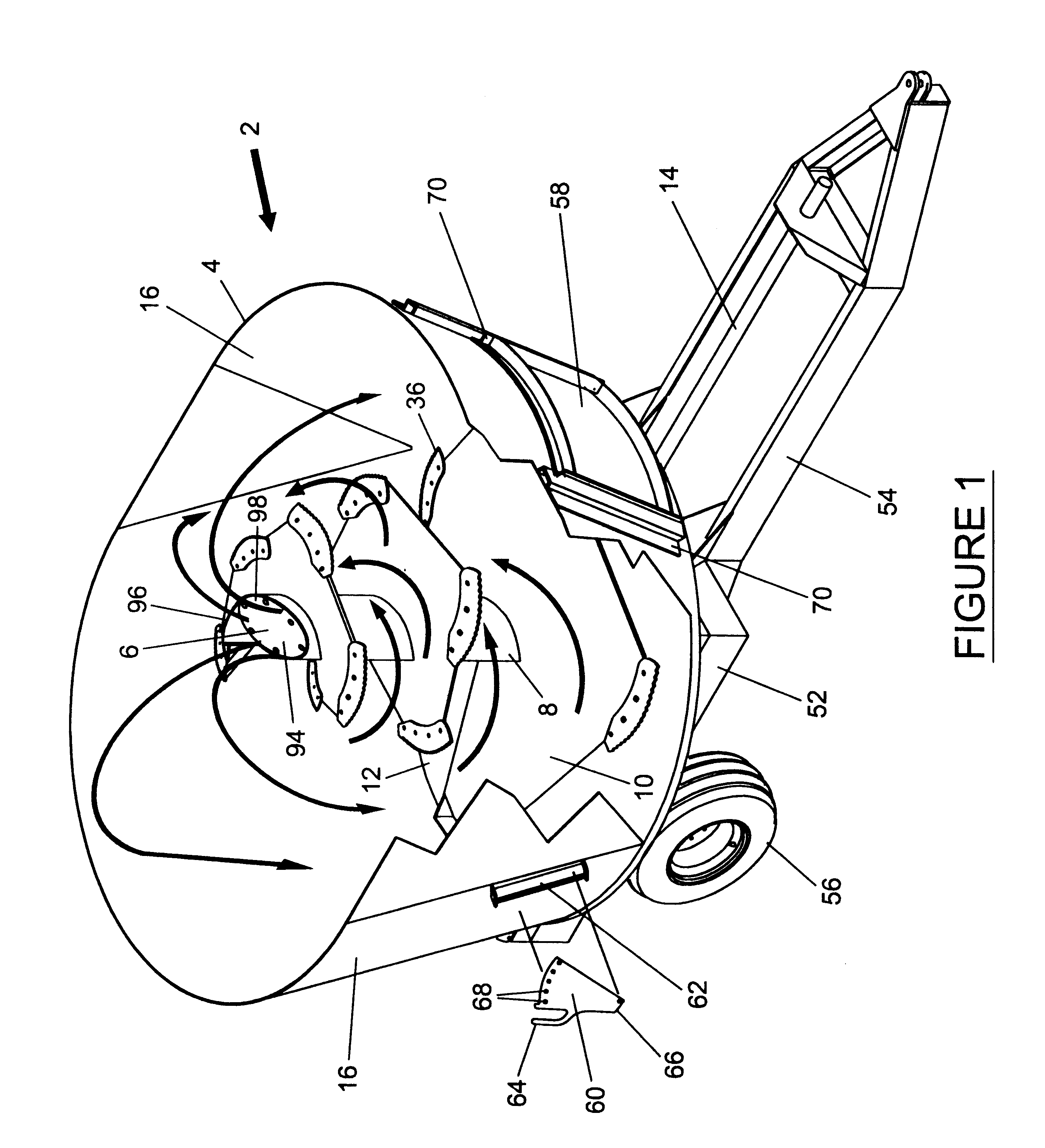
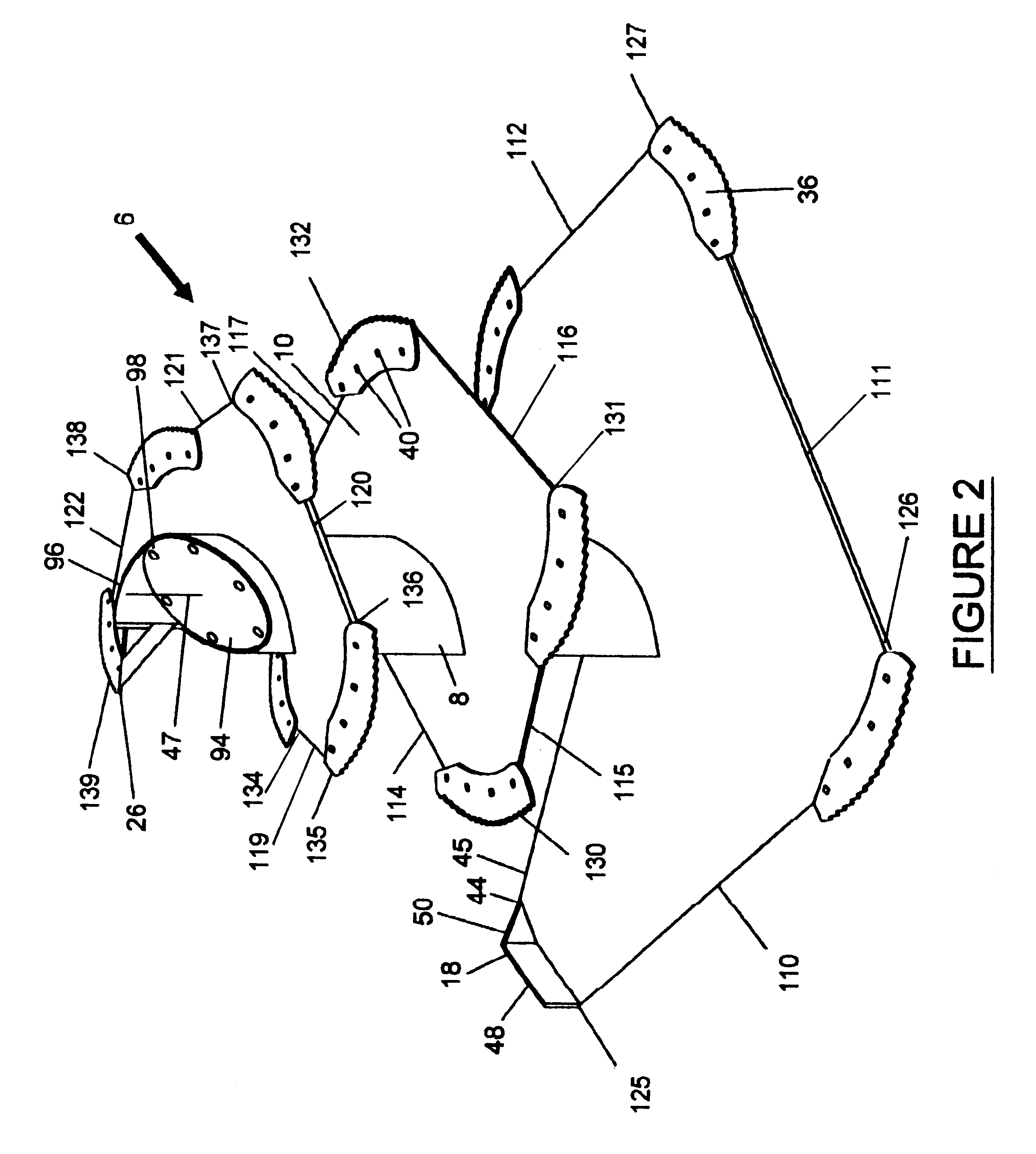
In FIGS. 1, 2 and 3, a vertical feed mixer 2 has a mixing chamber 4 containing an auger 6. The auger is vertically mounted to rotate within the chamber 4 about its longitudinal center axis. The auger 6 has a center post 8 with a generally helically-shaped flight 10 extending from a top of said post 8 to a base thereof. The mixing chamber 4 has a floor 12 and the post 8 extends through the floor 12 to a gearing mechanism (not shown in FIG. 1) that is connected to a horizontal shaft 14. The post 8, the gearing mechanism (not shown in FIG. 1) and the shaft 14 are conventional. The flight 10 increases in size from the top of the auger 6 to the base thereof Just above the floor 12, the flight 10 is preferably sized to extend almost to an interior of a wall 16 of the chamber 4. The wall 16 diverges from bottom to top of the chamber 4.

Preferably, an outermost edge 18 has approximately a one-quarter inch clearance from the interior wall 16 as the auger rotates. The outermost edge 18 can be ...


PUM


Abstract

A vertical feed mixer has an auger with a center post that has an inclined upper surface that is substantially flat. Flights of varying shapes can be used. The upper part of the flight extends above the upper surface. The inclined upper surface increases the versatility and efficiency of the mixer since feed bales are unlikely to block the mixer.

Description

1. Field of the InventionThis invention relates to a vertical feed mixer for use in mixing animal feed and, in particular, hay in any form including round bales with other animal feed. In particular, this invention relates to a vertical feed mixer having an auger with a center post and a helical flight extending around said post where the post has an upper surface that is inclined relative to said center axis.2. Description of the Prior ArtFeed mixers of various forms are known and, in particular, feed mixers for mixing round bales of hay or haylage of any size, including large and small bales with other animal feedstuffs including corn silage, commodities, byproducts and concentrates are known. Previous vertical feed mixers have a vertically mounted auger having a helically-shaped expanding periphery that is narrowest at a top and increases in size towards the base. It is known to have blades mounted periodically along the periphery of the auger. The periphery is smoothly curved in...

Claims


Application Information

Patent Timeline
Patent Type & Authority Patents(United States)
IPC IPC(8): A01K5/00B01F13/00B01F15/00B01F7/24A01F29/06B01F7/00
CPCA01K5/004B01F7/00008B01F7/245B01F13/0035Y10S241/605Y10S366/603B01F27/05B01F27/9212B01F33/502
Inventor TAMMINGA, JACOB R.
Owner JAY LOR INT INC
Why Eureka
Try Eureka