
Needle sheath device

a needle sheath and needle technology, applied in the field of needle sheath devices, can solve the problems of high probability that the fluid at the needle could be splattered, splashed or aerosolized into the atmosphere, and achieve the effect of preventing aerosolization or splashing of blood and overcoming the potential for aerosolization or splashing

Inactive Publication Date: 2001-12-11
SMITHS MEDICAL ASD INC
View PDF109 Cites 72 Cited by
  • Summary
  • Abstract
  • Description
  • Claims
  • Application Information

AI Technical Summary

Benefits of technology

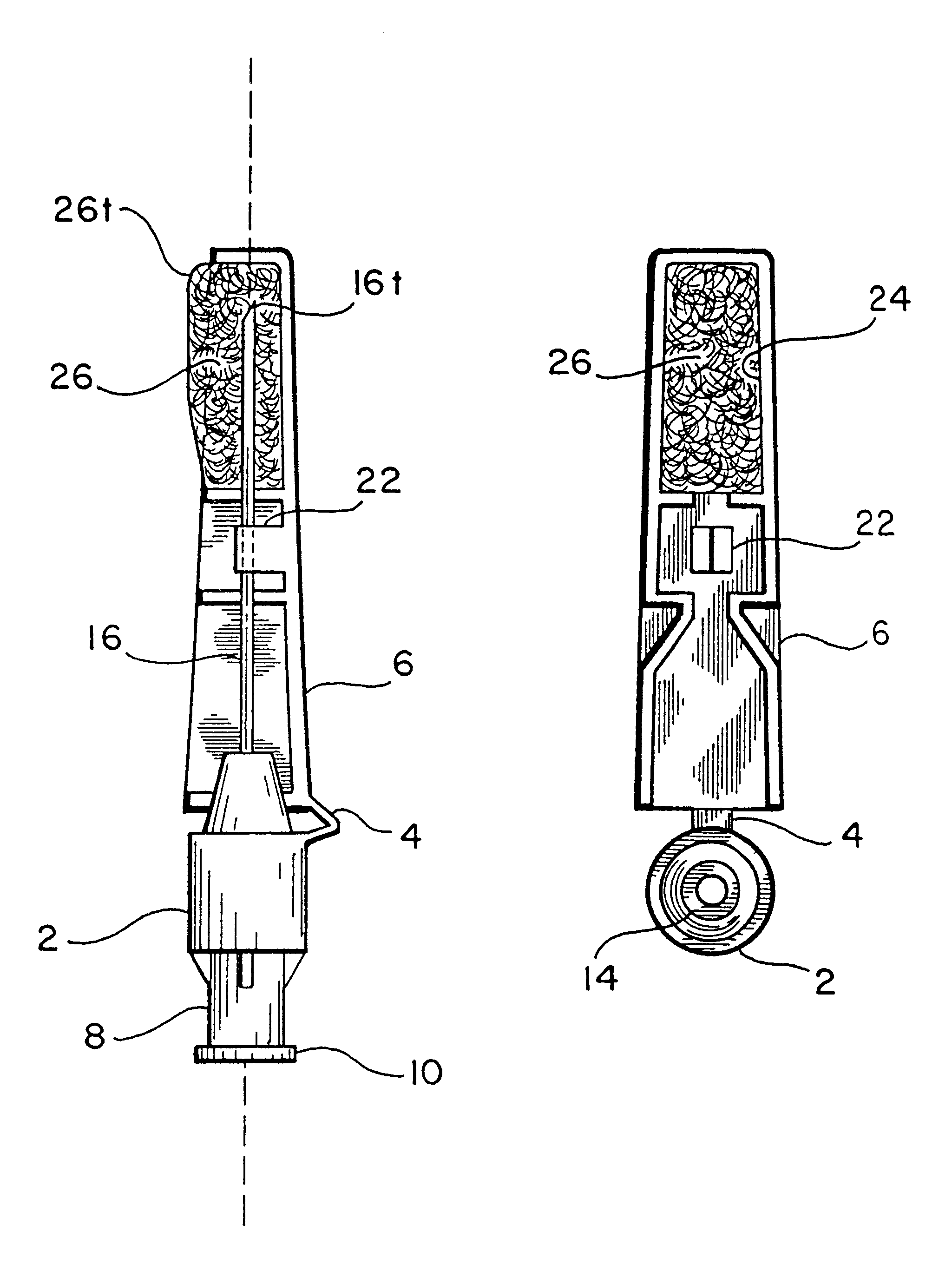
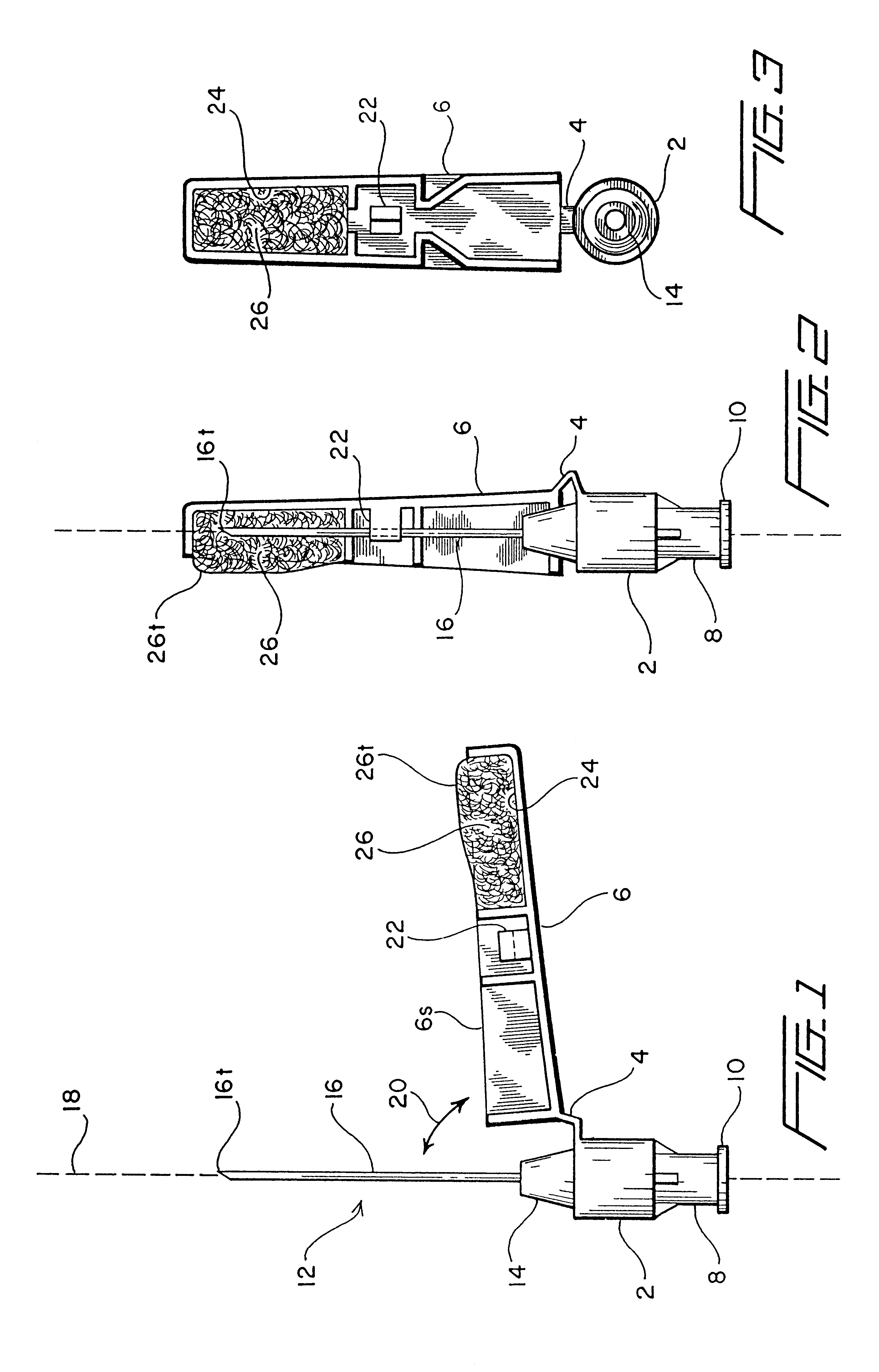
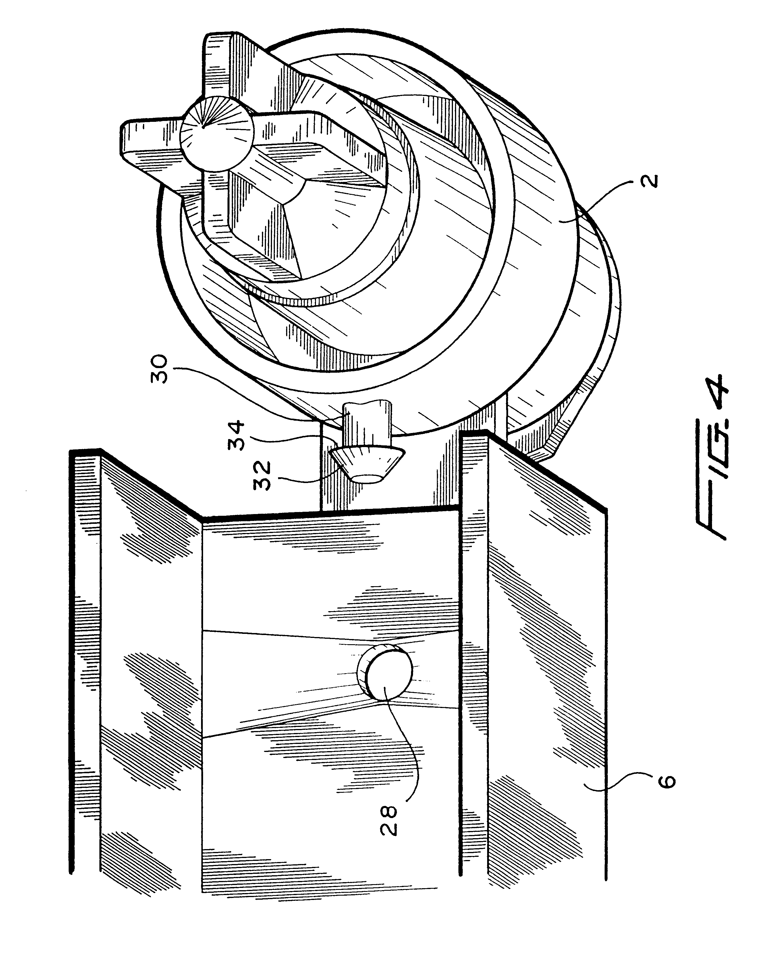
Specifically, to overcome the potential aerosolization or splashing of fluid when a needle sheath is pivoted to enclose a contaminated needle, a fluid absorbable material yieldable to a needle pressed thereagainst is provided to the upper portion of the needle sheath so that, as the needle is being enclosed by the being pivoted needle sheath, the needle would contact the fluid absorbable material. To ensure contact, the absorbable material is configured such that a portion thereof extends to a position whereby, if the needle sheath were to have integrated thereto a locking mechanism that fixedly retains the needle when the needle sheath is pivoted to be in substantial alignment with the needle, the absorbable material would first contact the needle so that whatever fluid that may have been collected at the needle is absorbed thereby, before the needle contacts the locking mechanism. Insofar as fluid collected at the needle is absorbed by the fluid absorbable material before the needle contacts the locking mechanism, any vibration of the needle due to contact between the locking mechanism and the needle which otherwise would have flicked the fluid from the needle is prevented.
It is therefore an objective of the present invention to provide a safety device that prevents aerosolization or splashing of blood when a needle sheath is pivoted to fixedly retain the needle.

Problems solved by technology

However, given the fact that fluid, such as for example blood or medicament, could potentially be collected at the needle, and more specifically at the tip thereof, it has been found that there is a high likelihood that the fluid at the needle could be splattered, splashed or aerosolized into the atmosphere when the protective housing is pivoted to enclose the needle.

Method used


Image

  • Needle sheath device
  • Needle sheath device
  • Needle sheath device

Examples


Embodiment Construction

A safety device of the instant invention is shown in FIG. 1. There, a base 2 is shown to have connected thereto, by means of a flexible strap or living hinge 4, a housing or sheath 6. Base 2 has an extension 8 to which a circumferential lip 10 is provided at its end for mating with a fluid container, for example a syringe (not shown). A needle assembly 12 is mated to the other end of base 2, by way of a hub 14. Thus, needle 16 is fixed to base 2 along a longitudinal axis, designated 18.

As shown by its partially cut view, sheath 6 is connected to base 2, by hinge 4, such that it is pivotable bi-directionally as indicated by bi-directional arrow 20. In FIG. 1, sheath 6 is shown to be at a position away from longitudinal axis 18 such that needle 16 may be used either to provide medicament to or withdraw blood from a patient. After use, oftentimes needle 16 has at tip 16t thereof (or at that portion of the needle) droplet(s) of blood.

Using FIG. 1 for illustration, before the instant inv...


PUM


Abstract

The safety device of the instant invention is equipped with a fluid absorbable material at the portion of the sheath that meets the tip portion of the needle so that, as the sheath is pivoted to a position in substantial alignment with the needle, whatever fluid that has been collected at the needle is absorbed before the needle is fixedly retained by a locking mechanism, either integrated within the needle sheath or to the base and lower portion of the needle sheath, to thereby prevent splattering or aerosolization of contaminated fluid into the environment.

Description

The instant invention relates to a safety device for housing a hypodermic needle to prevent the tip of the needle from being exposed after use and particularly to a needle sheath that includes a material for absorbing any fluid collected at the needle when the sheath is positioned to enclose the needle.In Hollister U.S. Pat. No. 4,982,842 there is disclosed a safety needle device comprising a housing hingedly connected to a base of the device. The housing is pivotable to a position in substantial alignment with a needle mated to the device so as to enclose the same. The '842 device has proven to be quite effective in preventing accidental needle pricks.However, given the fact that fluid, such as for example blood or medicament, could potentially be collected at the needle, and more specifically at the tip thereof, it has been found that there is a high likelihood that the fluid at the needle could be splattered, splashed or aerosolized into the atmosphere when the protective housing...

Claims


Application Information

Patent Timeline
Patent Type & Authority Patents(United States)
IPC IPC(8): A61M5/32A61M5/31
CPCA61M5/3216A61M2005/3109
Inventor HOLLISTER, WILLIAM H.
Owner SMITHS MEDICAL ASD INC
Learn More