Ultrasonic method and apparatus for automatically controlling moving doors

Inactive Publication Date: 2001-12-11
ASSA ABLOY IP
View PDF6 Cites 27 Cited by
  • Summary
  • Abstract
  • Description
  • Claims
  • Application Information

AI Technical Summary

Benefits of technology

According to still further features in the described preferred embodiment, the determined door position controls the closing of the door by applying, during the initial and final closing movements of t

Problems solved by technology

However, optical systems generally require wiring within the door, which is expensive to install and to maintain.
Further, the detection is effective with respect to limited confined areas through which th

Method used


Image

  • Ultrasonic method and apparatus for automatically controlling moving doors
  • Ultrasonic method and apparatus for automatically controlling moving doors
  • Ultrasonic method and apparatus for automatically controlling moving doors

Examples


Example

As indicated above, the invention is described below with respect to the method and apparatus illustrated in my patent application U.S. Ser. No. 09 / 245,742, filed Feb. 8, 1999.

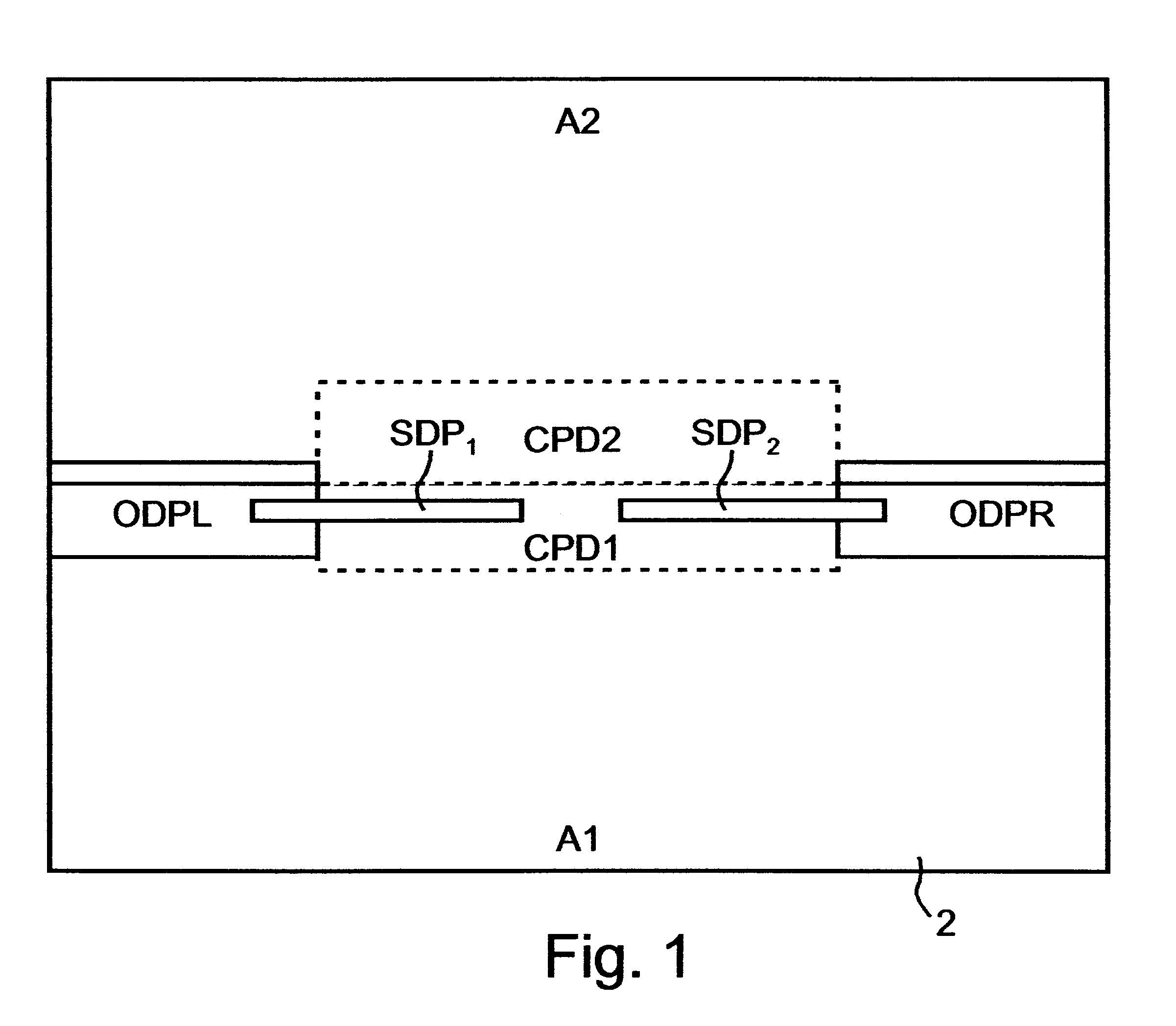
FIG. 1 diagramatically illustrates, in top plan view, a sliding door in the form of a pair of sliding door panels SDP.sub.1, SDP.sub.2 movable to their closed positions and to their open positions over a floor 2 to control the flow of traffic through a passageway defined by the door panels. The area on each side of the two sliding door panels SDP.sub.1, SDP.sub.2, is divided into the following: a predetermined approach area A1, A2 located in front of the sliding door panels on each side thereof; an opening-door protect area ODPL (left), ODPR (right), laterally outwardly of the outer ends of the sliding door panels when in their closed positions; and a closing-door protect area CDP1, CDP2, between the inner ends of the sliding door panels when in their open positions.

As described in my above-cited application, ...


PUM


Abstract

A method and apparatus for automatically controlling the movement of a door over a floor from an open position to a closed position with respect to a door frame, by mounting ultrasonic transmitters at one side of the door frame and oriented to transmit ultrasonic energy downwardly towards the floor and to reflect the energy from the floor upwardly upwardly at the other side of the door frame; mounting ultrasonic receivers over the door frame at the opposite side and oriented to receive the energy from the ultrasonic transmitter reflected by the floor; and processing the reflected energy received by the ultrasonic receiver to detect the presence of an object in the path of the door, when moving toward its closed position, and to automatically interrupt the closing of the door.

Description

FIELD AND BACKGROUND OF THE INVENTIONThe present invention relates to an ultrasonic method and apparatus for automatically controlling the opening and closing of moving doors, particularly sliding doors.Automatic door control systems are gaining wide-spread use in order to control traffic into or out of enclosed spaces which are heated or cooled by airconditioning systems. Such door control systems not only must detect and respond to objects moving towards the closed doors, but must also provide protection against injury by a closing or opening door, and further, should minimize the time the door is in the open condition in order to minimize wastage of the energy used for airconditioning the enclosed space.My above-cited patent application describes a method and apparatus for automatically controlling the opening and closing of a door movable over a floor, and a drive for driving the door to its open and closed positions, by: (a) ultrasonically monitoring a predetermined approach ar...

Claims


Application Information

Patent Timeline
IPC IPC(8): G01S15/04G01S15/00E05F15/00
CPCG01S15/04E05F2015/433E05F15/43E05Y2900/132
Inventor ARIAV, ARIE
Owner ASSA ABLOY IP
Why Eureka
Try Eureka