Laser telemeter

a laser telemeter and laser technology, applied in the field of laser telemeters, can solve the problems of increasing the dimensions of the optical system, affecting reducing the accuracy of the laser,

Inactive Publication Date: 2001-12-11
LEICA GEOSYSTEMS AG
View PDF6 Cites 21 Cited by
  • Summary
  • Abstract
  • Description
  • Claims
  • Application Information

AI Technical Summary

Problems solved by technology

The maximum laser power is limited on the one hand by regulations relating to safety for the eyes and moreover by the capacity of the energy source for operating the laser.
The disadvantages of increasing the dimensions of the optical systems are the associated inconvenience of handling and greater weight.
The technical complexities associated with a larger range have led to the development and optimization of specially designed laser telemeters for different ranges.
The readiness of the devices for use additionally depends on the weather conditions, which may hinder the transmission of the optical radiation.
A device designed for relatively long ranges may, under unfavorable circumstances therefore, also be used for shorter distances at which the device designed for these ranges has failed.
However, the disadvantage is that only the limited field of view designed for more remote targets is constantly available for the target observation.
In case of doubt, the users will nevertheless have to decide in favor of the technically more complex, and therefore more expensive, device.

Method used


Image

  • Laser telemeter
  • Laser telemeter
  • Laser telemeter

Examples


Embodiment Construction

The invention has also been disclosed in related German patent application No. 198 29 659.2, filed Jul. 2, 1998, which is hereby incorporated by reference.

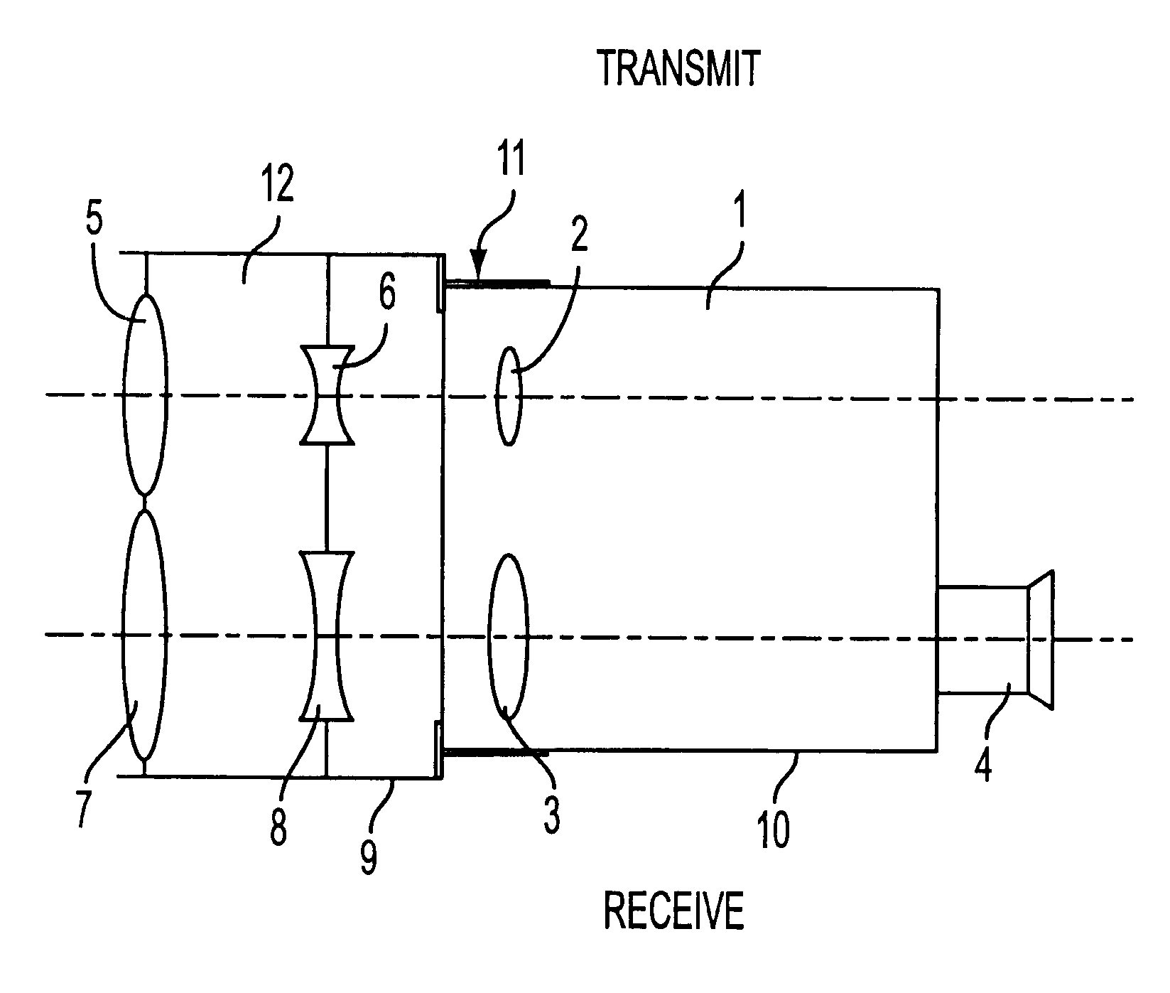
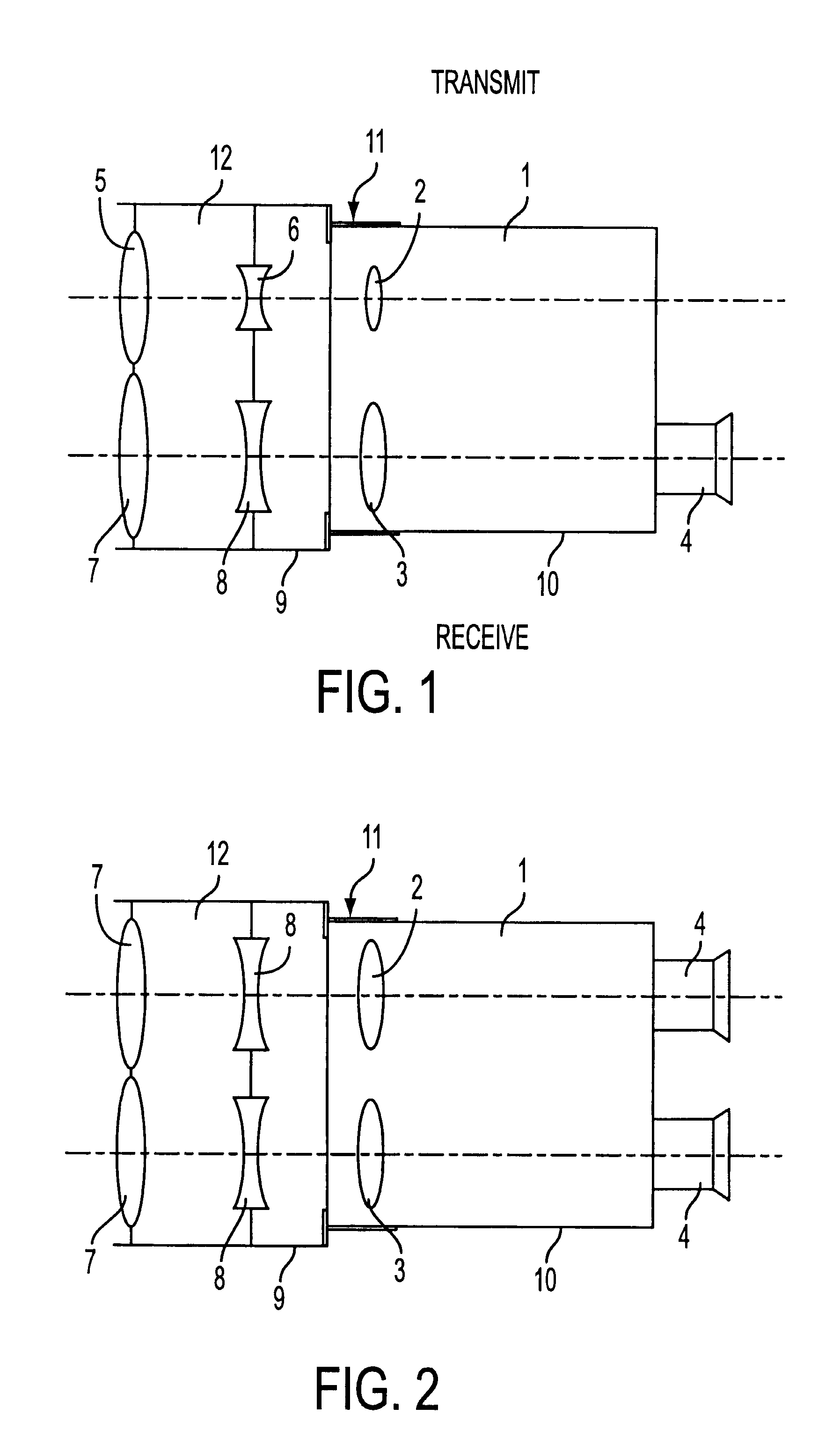
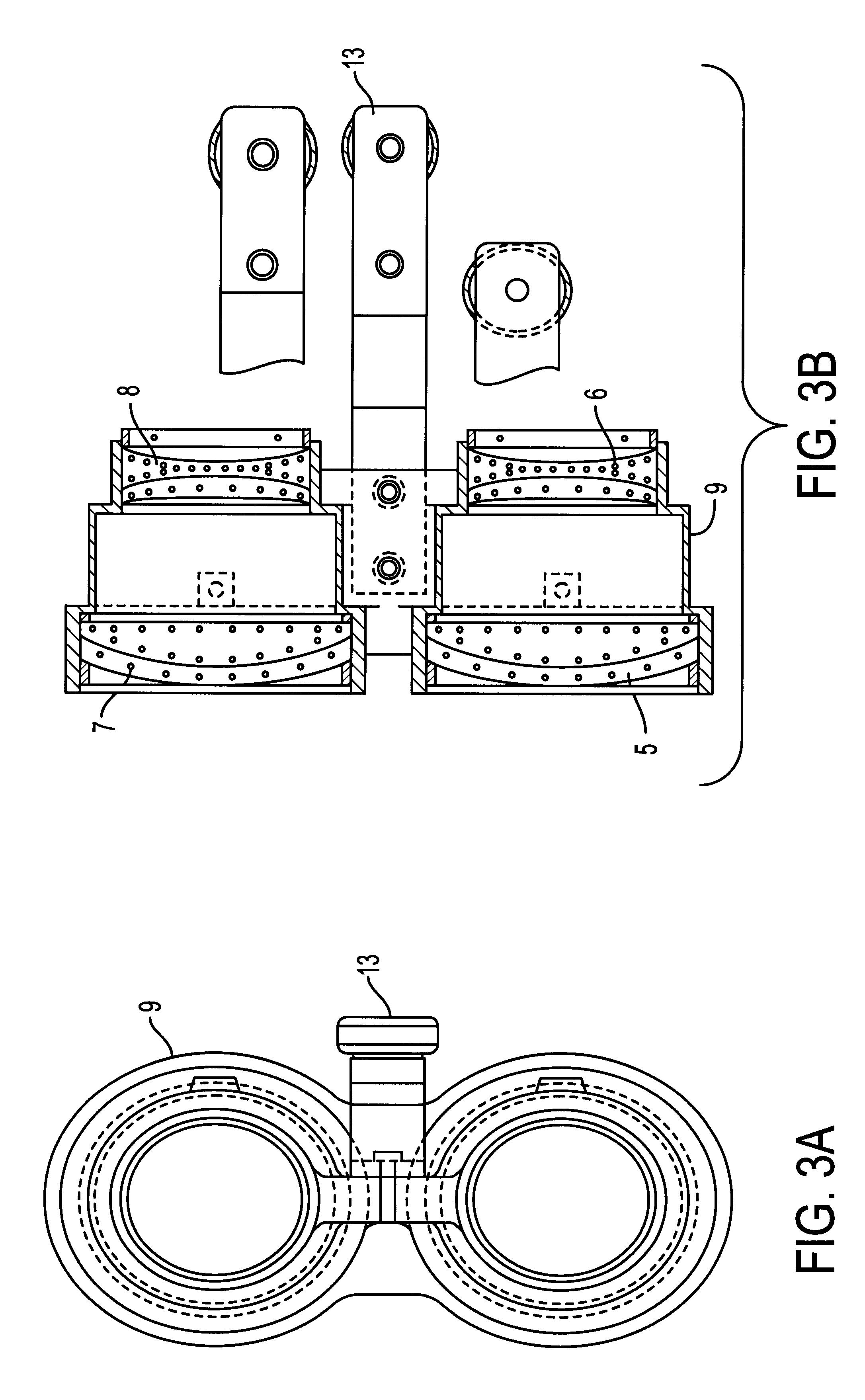
In the drawings, embodiments of the laser telemeter according to the invention are shown schematically. They are described in more detail below with reference to the Figures.

The invention starts from a basic configuration of a laser telemeter and, if required, increases the range by means of a telescope optical system which can be inserted. Although such a telescope optical system is known per se from "Die Fernrohre und Entfernungsmesser" [The telescopes and telemeters], Dr. A. Konig, (1937), page 95, it is discussed there only from the point of view of a change in magnification. The positive effects on the intensity balance in the transmitted and received beam are not directly evident. However, these are of decisive importance for an increase in the range, in particular in the case of small targets. Although the change in magnifi...


PUM


Abstract

A laser telemeter having separate transmitting and receiving optical systems, and at least monocular target observation, in which a telescope optical system (5, 6) which is inserted before the transmitting optical system (2) and reduces the divergence of the transmitted beam, a telescope optical system (7, 8) which is inserted before the receiving optical system (3) and has an aperture angle adapted to the divergence of the transmitted beam and a common support frame (9) for the telescope optical systems (5, 6; 7, 8) which can be coupled at the front with the housing (10) of the laser telemeter (1) are provided.

Description

1. Field of the InventionThe invention relates to a laser telemeter having separate transmitting and receiving optical systems, and at least monocular target observation.2. Description of the Related ArtThe majority of the known laser telemeters are based on the following principle. A collimated laser beam is produced and is directed via a transmitting optical system at a remote target. The laser light reflected by the target is picked up by the receiving optical system and fed to a detector. The receiving optical system is usually also used for target observation. Such a device is disclosed, for example, in German Publication DE 41 35 615 A1. A binocular observation device with a laser telemeter is disclosed in German Publication DE 37 04 848 A1.Particularly in the case of small targets, it is necessary to collimate the laser beam well. It is desirable for the distance-dependent size of the laser spot to be smaller than the cross-section of the target to be measured, in order both ...

Claims


Application Information

Patent Timeline
Patent Type & Authority Patents(United States)
IPC IPC(8): G01C3/04G01C3/02G02B23/00G01S7/481
CPCG01C3/04G01S7/481G01S7/4813G02B23/00
Inventor ZADRAVEC, DUSAN
Owner LEICA GEOSYSTEMS AG
Why Eureka
Try Eureka