
Hydraulic circuit for turning excavator

a hydraulic circuit and excavating technology, applied in the direction of fluid couplings, servomotors, couplings, etc., can solve the problems of no conventional hydraulic circuit system designed, too low pressure oil to operate at such a hopeful speed, complicated and expensive problems

Inactive Publication Date: 2001-12-18
YANMAR CO LTD
View PDF13 Cites 41 Cited by
  • Summary
  • Abstract
  • Description
  • Claims
  • Application Information

AI Technical Summary

Problems solved by technology

However, with respect to the conventional hydraulic system, each hydraulic actuator is supplied with pressure oil from a single hydraulic pump, thereby being too low in quantity of pressure oil to be operated at such a hopeful speed.
Hei 8-134960 is further provided with such purpose-built circuit for increasing the operation speed, thereby being complicated and expensive.
Moreover, the check valve in the joining circuit cannot limit the amount of joined oil flow for restricting the increasing of the operation speed.
However, there is no conventional hydraulic circuit system designed with said case in mind so as to give the arm priority over the boom when the both are operated simultaneously.
Also, supposing a small excavator employs this hydraulic circuit system, the hydraulic pressure for turning operation of the main body is to be limited low.
However, as the pressure oil for turning the main body flows into the hydraulic circuit for driving the boom, the boom may be moved too fast.
The operation speed of the boom cannot be limited because the oil flowing from the above said joining circuit to the hydraulic circuit for the hydraulic actuator for the boom cannot be shut off.

Method used


Image

  • Hydraulic circuit for turning excavator
  • Hydraulic circuit for turning excavator
  • Hydraulic circuit for turning excavator

Examples


Embodiment Construction

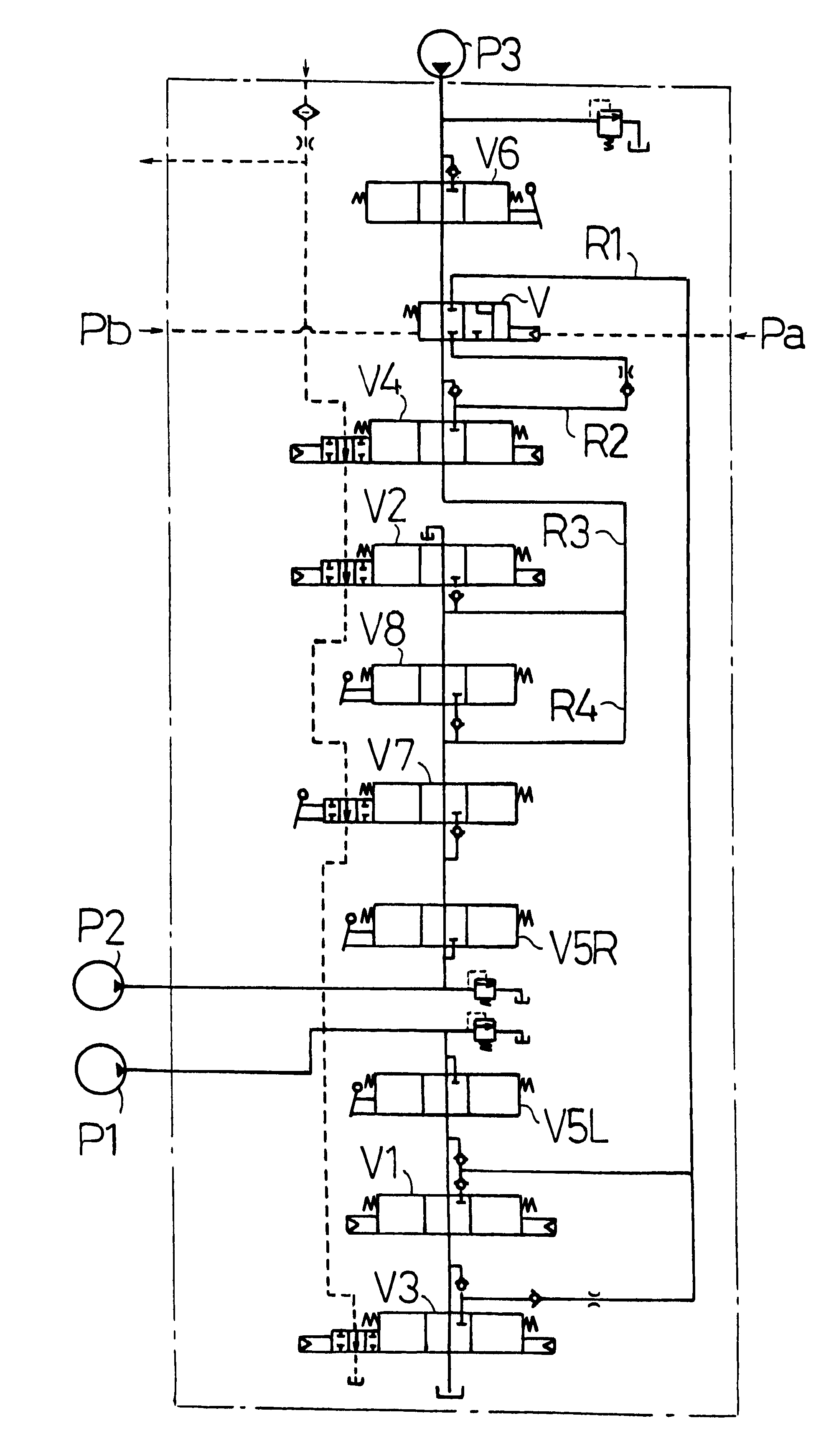
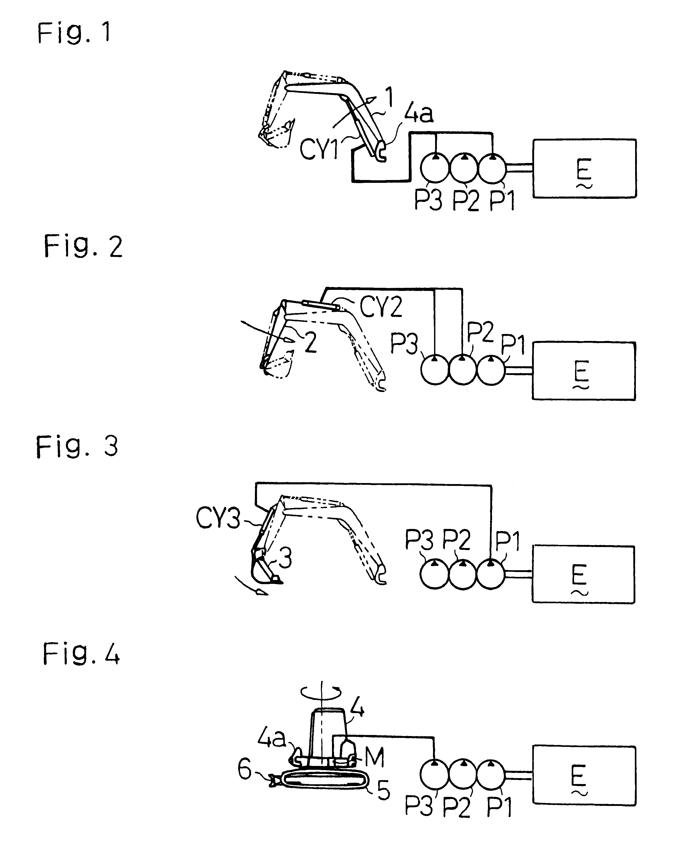
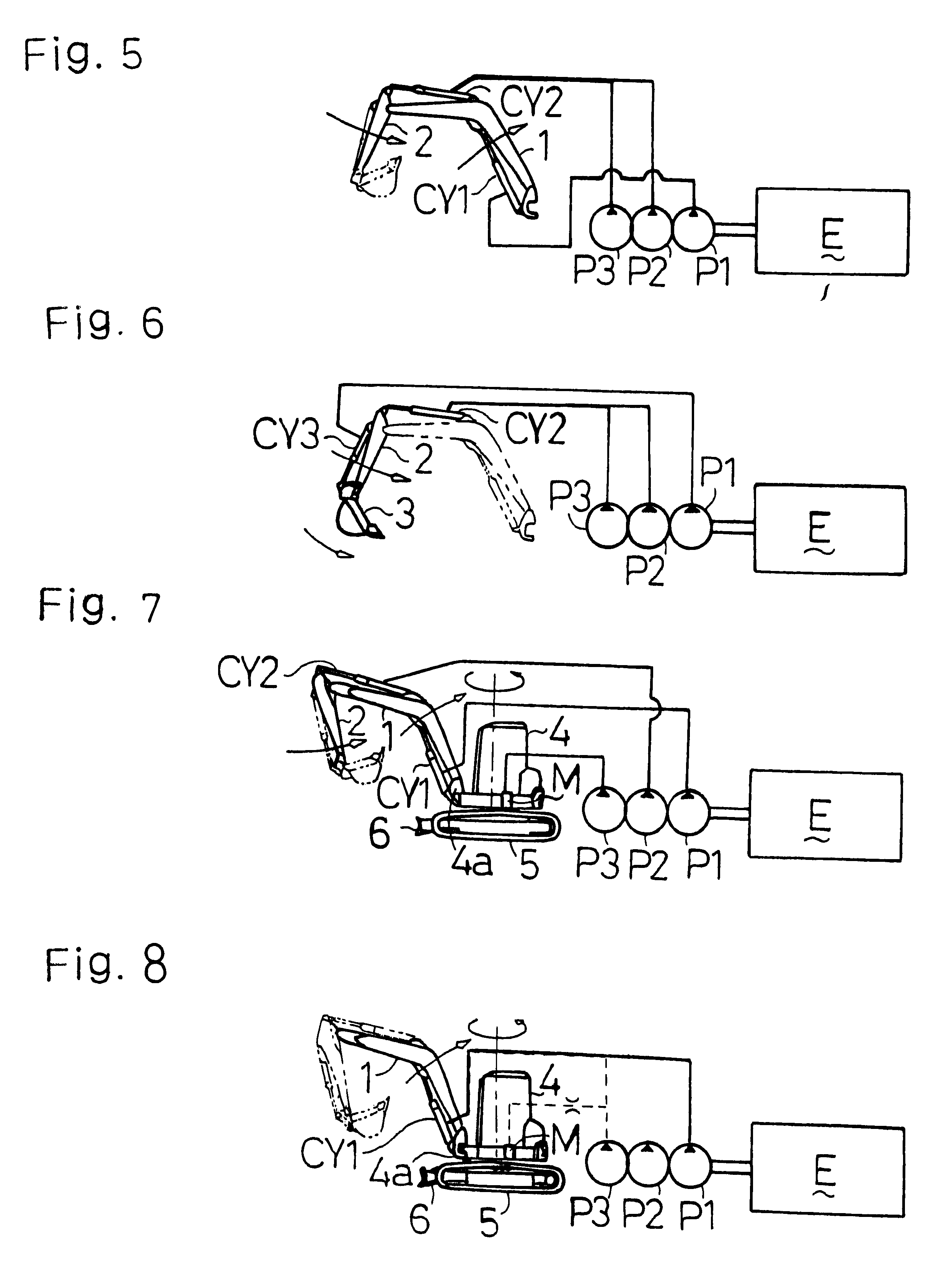
At first, explanation will be given on a general construction of a turning excavator of the present invention. As shown in FIGS. 1 through 8, a main body 4 is rotatably mounted over a crawler type travelling device 5. A boom 1 is pivoted at the basic end thereof onto the front end of the main body 4. An arm 2 is pivoted at the basic end thereof onto the utmost end of the boom 1. A bucket 3 is pivoted at the basic end thereof onto the utmost end of the arm 2. The boom 1, arm 2 and bucket 3, serving as working arms, are driven by hydraulic actuators of a boom cylinder CY1, an arm cylinder CY2 and a bucket cylinder CY3, respectively. The main body 4 is turned about the travelling device 5 by a turning motor M serving as a hydraulic actuator.

In addition to the above mentioned hydraulic driving means, the travelling device 5 is provided with left and right hydraulic travelling motors ML and MR, which can be driven independently to each other. As shown in FIG. 4 or others, a blade 6 is pr...


PUM


Abstract

A hydraulic circuit which, when applied to a turning excavator having hydraulic actuators for the working arms and the turning excavator body supplied with pressure oil from three pumps, can increase the operation speed of the booms and arms without providing a separate hydraulic pump to improve the work efficiency. During the individual driving, the boom cylinder (CY1) is supplied with a pressure oil from the first and third pumps (P1, P3), the arm cylinder (CY2) from the second and third pumps (P2, P3), the bucket cylinder (CY3) from the first pump (P1), and the turning motor (M) from the third pump (P3). During the simultaneous driving of the boom and arm cylinders (CY1, CY2), the arm is supplied with an operation speed increasing pressure oil from the third pump (P3). When the boom cylinder (CY1) and the turning motor (M) are simultaneously operated, a part of the pressure oil to the turning motor (M) from the third pump (P3) is supplied to the boom cylinder (CY2).

Description

SPECIFICATION1. Field of the ArtThe present invention r elates to a hydraulic circuit system having at least three hydraulic pumps for supplying hydraulic actuators of a turning excavator with pressure oil, wherein working arms consisting of a boom, an arm and a bucket are operated and a turning excavator body is turned by the respective hydraulic actuators.2. Background ArtConventionally, it is a well-known technique for a turning excavator having a turning excavator body (a main body) and working arms consisting of a boom, an arm and a bucket to provide the hydraulic circuit system thereof with three hydraulic pumps for supplying hydraulic actuators for respectively driving the boom, the arm, the bucket and the main body with pressure oil, wherein each actuator is supplied with pressure oil by one of the pumps whether the actuators are driven one by one at different times (individually) or more than one of those are driven simultaneously.For increasing the operation speed of each ...

Claims


Application Information

Patent Timeline
IPC IPC(8): E02F9/22F15B11/02
CPCE02F9/2239E02F9/2282E02F9/2292
Inventor KONDO, MASAMI
Owner YANMAR CO LTD
Features
  • Generate Ideas
  • Intellectual Property
  • Life Sciences
  • Materials
  • Tech Scout
  • Unparalleled Data Quality
  • Higher Quality Content
  • 60% Fewer Hallucinations
Learn More