Water resistant window frame

a window frame and water-resistant technology, applied in the direction of sills/thresholds, wing arrangements, rain/draught deflectors, etc., can solve the problems of egress opening, detracting from the appearance of the exposed interior height of the window frame,

Inactive Publication Date: 2002-01-01
ROYAL GROUP
View PDF5 Cites 92 Cited by
  • Summary
  • Abstract
  • Description
  • Claims
  • Application Information

AI Technical Summary

Problems solved by technology

However, this increases the exposed interior height of the window sill detracting from its appearance and reducing the egr

Method used


Image

  • Water resistant window frame
  • Water resistant window frame
  • Water resistant window frame

Examples


Embodiment Construction

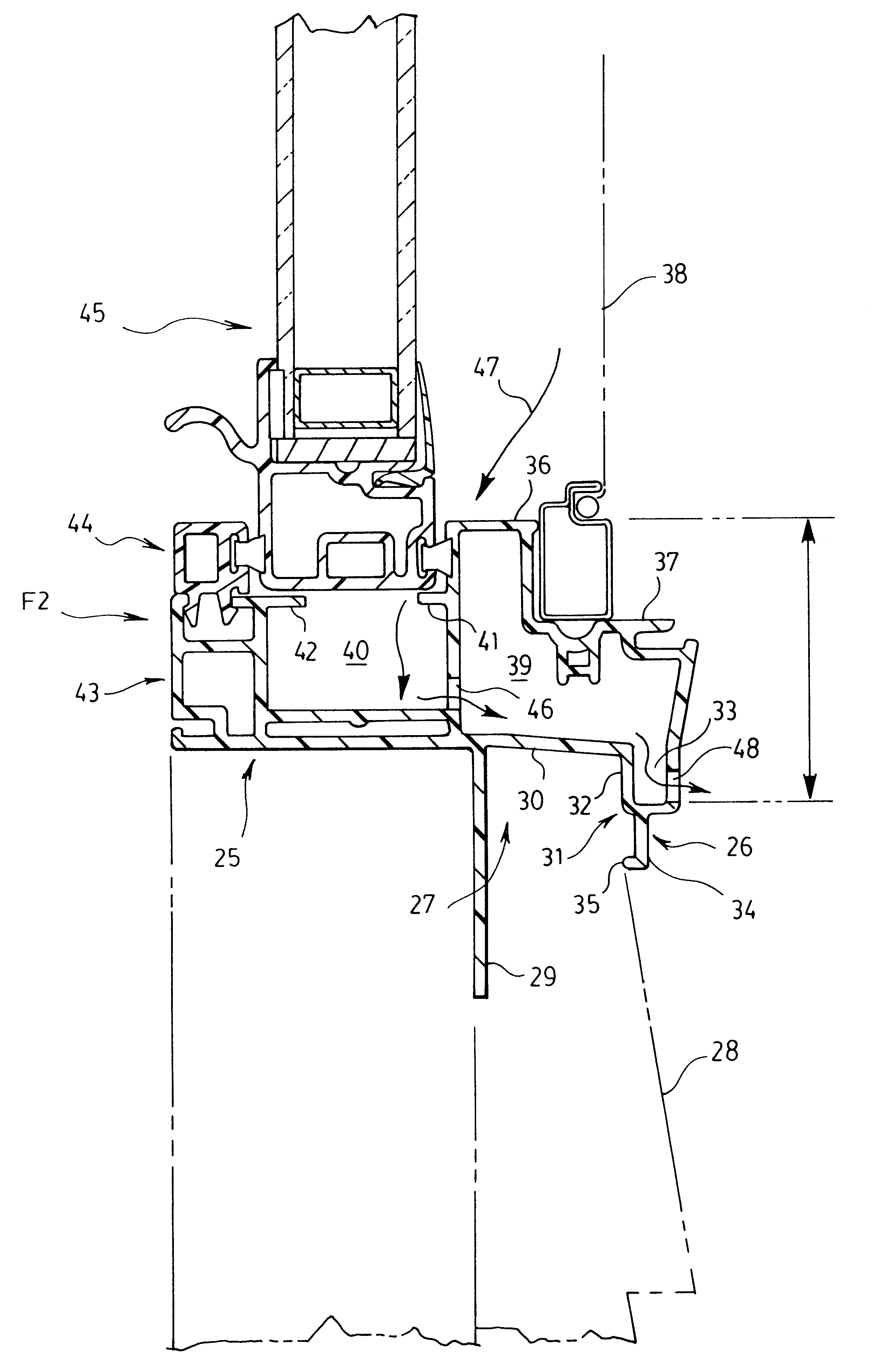
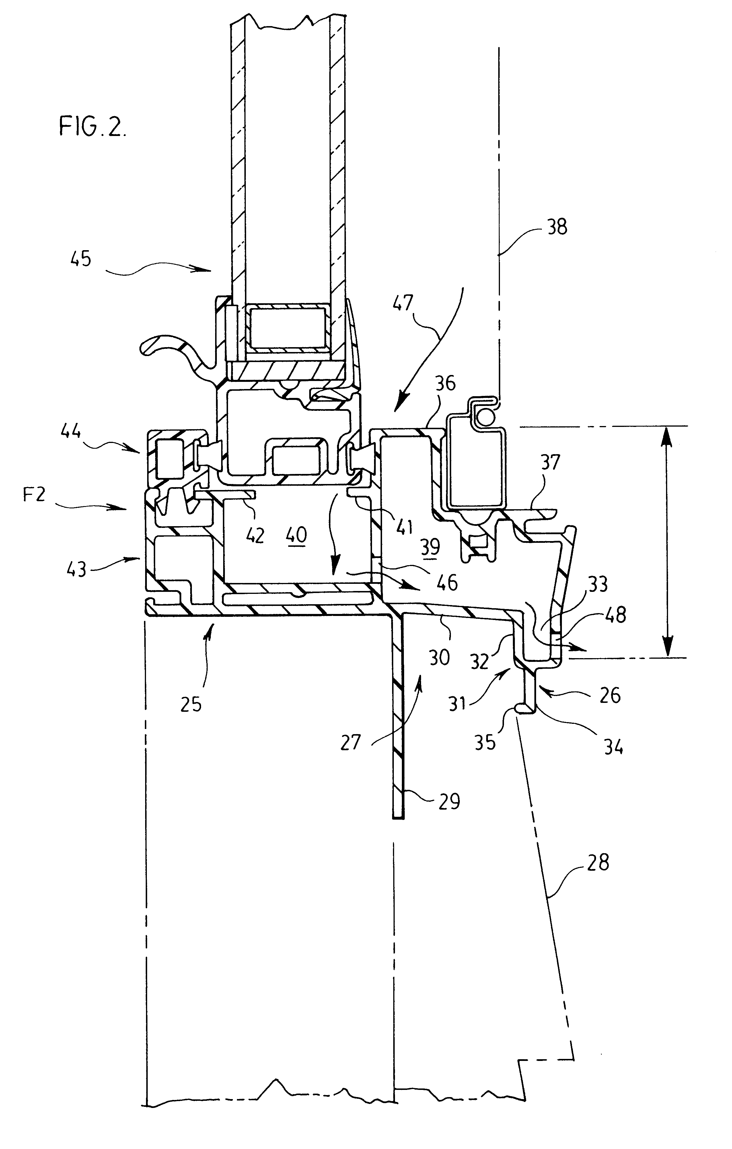
FIG. 2 illustrates a window frame unit designated as F2 which achieves the desired water resistance represented by the dam height X while reducing the exposed interior height at the sill of the window frame thus increasing the size of the egress opening and increasing the aesthetic appearance of the window interior.

FIG. 2 is a view similar to FIG. 1 but showing a section through the sill of the frame F2 which has been modified to incorporate the invention. Frame F2 has a body portion 25 corresponding to the body portion 1 of the frame F1. The body portion 25 carries an integral J-rail return member designated at 26 which is modified from the J-rail return 2 of FIG. 1 but does provide a J-channel 27 for receiving siding 28.

The J-rail return 26 comprises a nailing fin or flange 29 portion corresponding to the nailing fin 3 in FIG. 1, an outwardly projecting arm or portion 30 and a return portion generally designated at 31. This return portion 31 comprises a double walled section 32 fo...


PUM


Abstract

A window frame incorporating a sliding sash, the frame providing increased water resistance by incorporating an integral J-rail return, the return portion of which has a double wall to provide a depending trough at the bottom of the frame with a wall forming a chamber including the trough, opening from the bottom of the frame into the chamber and from the bottom of the trough to the exterior to provide increased dam height against water backing up and spilling over the interior sill of the frame.

Description

This invention relates to a window frame construction for receiving and supporting a sliding window sash,, the frame to be mounted in a window opening in a wall of a structure, the window frame incorporating a J-rail return member to overlie siding applied to the exterior of the structure.More particularly, the invention is directed to such a window frame that provides increased water resistance for a minimized exposed interior sill frame height and hence increased egress opening, the frame also providing increased stiffness or strength, resistance to impact, and reduced costs of material.In the prior art there are many window frames which include a window retaining body portion for insertion into an opening in the wall of a building structure to circumscribe the interior of the opening and a nailing flange or fin circumscribing the exterior of the opening.Many such window frames also include a J-rail return member or which comprises a nailing fin member, a member projecting outward...

Claims


Application Information

Patent Timeline
IPC IPC(8): E06B1/70E06B3/44E06B3/32E06B7/26E06B7/00
CPCE06B1/702E06B3/44E06B7/26E06B2003/4492E06B2003/4461
Inventor EDGER, RONALD FREDRICK
Owner ROYAL GROUP
Why Eureka
Try Eureka