Snowmaking machine

a technology of snowmaking machine and pulverizer, which is applied in the field of snowmaking machines, can solve the problems of drawbacks of air-blowing pulverizers

Inactive Publication Date: 2002-01-01
SNOWMAGIC
View PDF8 Cites 16 Cited by
  • Summary
  • Abstract
  • Description
  • Claims
  • Application Information

AI Technical Summary

Problems solved by technology

However, the above air-blowi

Method used


Image

  • Snowmaking machine
  • Snowmaking machine
  • Snowmaking machine

Examples


embodiments

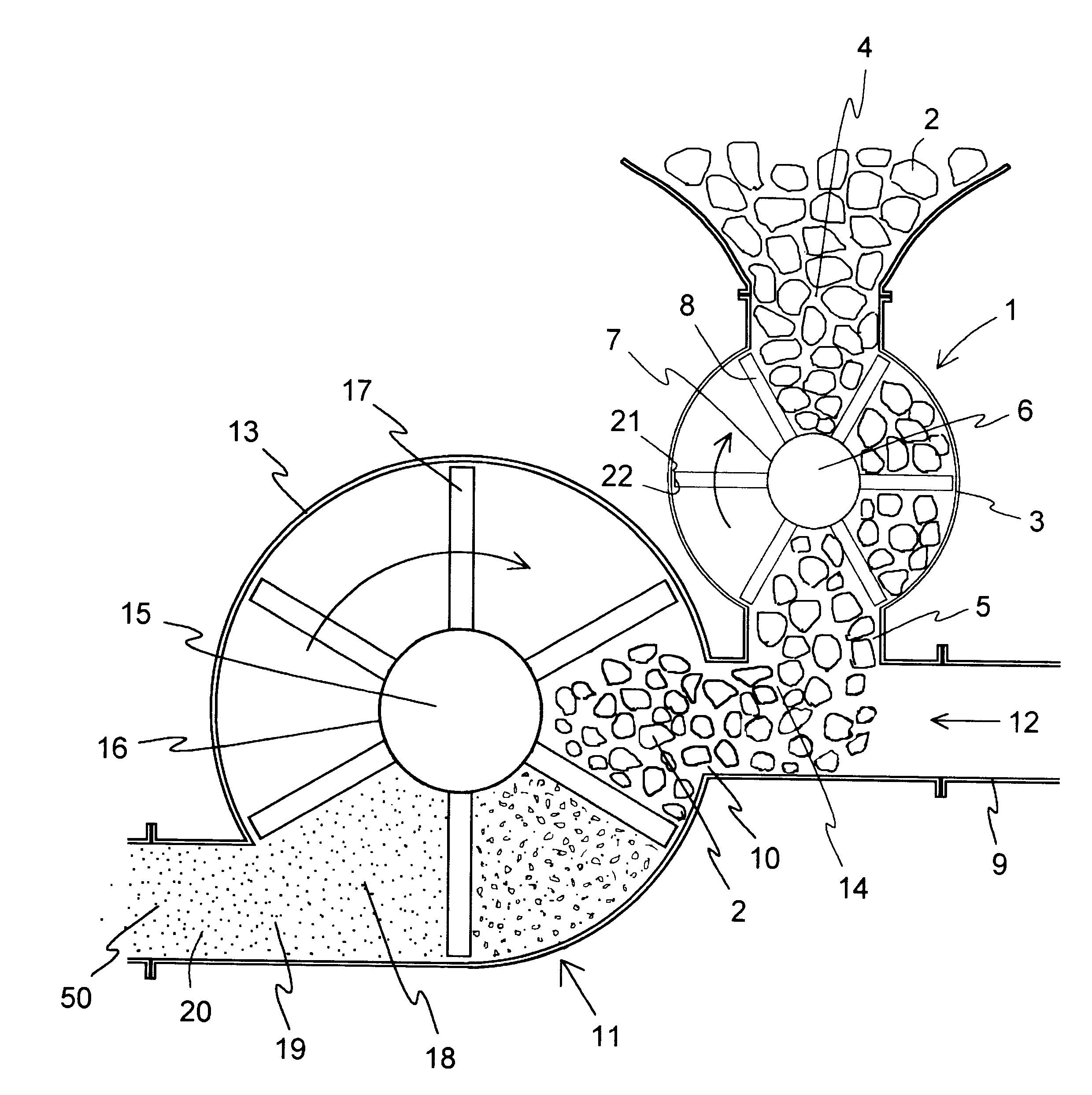
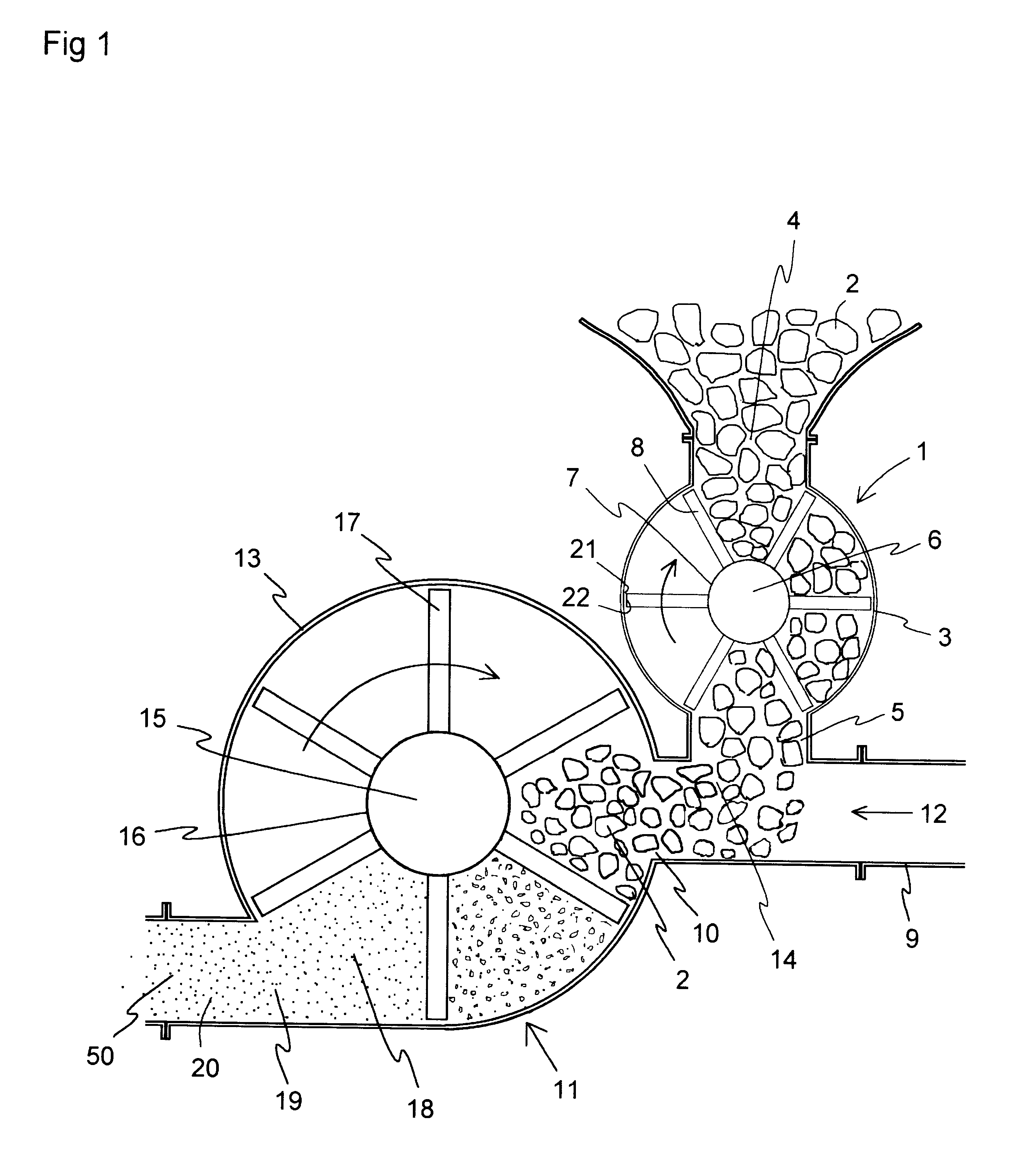
The following describes embodiments of the present invention in reference to the drawings. FIG. 1 is a schematic configuration of the present invention showing artificial snow making equipment with constant forced blowing wherein the front wall is removed to show the inside configuration. Number 1 is an ice block supplier to supply ice blocks at a constant rate, placed on the upstream side of air-blowing pulverizer 11. An ice block supplier 1 to supply ice blocks at a constant rate has funnel-shaped ice block supply opening 4, which receives ice blocks 2 as a raw material, on the top of steel cylindrical casing 3. In casing 3, rotational shaft 6 is positioned at the center and is rotated by a drive (not show in the figure) in the direction indicated by an arrow. With rotary blades 8 comprised of six steel blades, the width of each blade is equal to the width of rotational shaft. Additionally, the blades reach the inner wall of casing 3 and are arranged at an equal distance from each...


PUM


Abstract

Artificial snow making equipment includes an air-blowing pulverizer which prevents fluctuation in the size of ice pieces by eliminating fluctuation in the amount of ice blocks being supplied also eliminates blocking by the ice blocks, as a result utilizing air effectively such that the ice pieces are blown out as artificial snow the requisite distance. The artificial snow making equipment with constant forced blowing includes ice block supplier 1 to supply ice blocks at a constant rate and air-blowing pulverizer 11. The ice block supplier 1 has ice block supply opening 4 through which ice blocks 2 are supplied, casing 3 which has ice block supply opening 4; rotary blades 8 which supply ice blocks 2 at a constant rate while rotating in casing 3; and exit for ice blocks 5 which is positioned under casing 3. The air-blowing pulverizer 11 has air duct 9 which receives air 12 as well as ice blocks 2 that are supplied from an ice block supplier 1; casing 13 which has opening 10 of air duct 9 on the side surface; rotary blades 17 which pulverize ice blocks 2 into ice pieces 18 and which is placed in casing 13; and air exhaust 19 which is formed on the side of casing 13 opposite from opening 10 of the air duct to blow ice pieces 18 as artificial snow 20. An exit for ice blocks 5 of an ice block supplier 1 to supply ice blocks at a constant rate is connected to ice block receiving slot 14 of air-blowing pulverizer 11 via air duct 9.

Description

The present invention relates to an artificial snow making equipment for an artificial ski slope wherein a block of ice is pulverized and blown away.RELATED ARTA conventional air-blowing pulverizer such as an ice crusher generates artificial snow 49 by pulverizing ice block 48 into sleet-like small pieces as shown in FIGS. 11 and 12. The equipment in FIG. 11 has rotary blades 45 for pulverizing which are arranged at an equal distance from each other in the radial direction around the rotational shaft in casing 44 on the top of rigid substrate 47. Air supply opening 41, through which air to glow artificial snow 49 is supplied, and ice supply opening 42, through which ice blocks are supplied, are placed at one end of substrate 47 under the lower end of casing 44. The other end of substrate 47 under casing 44, opposite from supply opening 42, has exhaust opening 43 through which artificial snow 49 made of pulverized ice is blown. Ice blocks 48 are supplied, together with air through ai...

Claims


Application Information

Patent Timeline
IPC IPC(8): F25C3/00F25C3/04B02C13/08B02C13/28F25C5/00F25C5/04
CPCB02C13/08B02C13/2804F25C3/04Y10S241/17F25C5/046F25C2303/042F25C5/002F25C2500/08F25C5/20
Inventor FUJIWARA, TAKAMASA
Owner SNOWMAGIC
Why Eureka
Try Eureka