Programmable waveform generator for a global positioning system

a global positioning system and generator technology, applied in the field of global positioning system programmable generators, can solve the problems of inconvenient approach for broadcasting g.p.s. navigation signals from space, inability to provide space-qualified components that are fast, and inability to achieve intermediate frequency too low,

Inactive Publication Date: 2002-01-01
HARRIS CORP
View PDF1 Cites 76 Cited by
  • Summary
  • Abstract
  • Description
  • Claims
  • Application Information

AI Technical Summary

Problems solved by technology

Although such an architecture can generally be used for communications systems, such an approach is not suitable for broadcast of the G.P.S. navigation signals from space.
One limitation is the availability of space-qualified components that are fast enough to perform the required processing.
This limitation results in an intermediate frequency that is too low to preclude harmonic interference in the resultant modulated signal.
Another limitation is that any time jitter on the D / A converter results in additional phase noise on the composite output signal, which can violate the very stringent G.P.S. requirements.
A third limitation is that bandpass filters are required for every mixer stage in the upconverter.
These amplitude variations are problematic regarding satellite efficiency.
Applying non-constant envelope signals to saturated amplifiers results in signal distortions that can impact navigation accuracy.
As set forth though, due to the speed capabilities of current space qualified components (FPGA's and D / A's for example), interference can be caused by mixer harmonics when the first If frequency is too low in relation to signal bandwidth.
Further, ringing of the bandpass filters in the mixer stages can also result in a non-constant envelope which results in further errors and reduced amplifier efficiency.
However, as will be evident to one skilled in the art, such an approach could still lead to ringing of the bandpass filters in the frequency up-converter 15 which in turn represents a significant risk in the development, certification and space use of such a linear modulator.
Accordingly, the envelope of the output signal 48 is not constant and hence undesirable.
However, as illustrated therein, a linear phase modulator 62 is required, therefore, such a configuration fails to remedy all of the aforementioned shortcomings.

Method used


Image

  • Programmable waveform generator for a global positioning system
  • Programmable waveform generator for a global positioning system
  • Programmable waveform generator for a global positioning system

Examples


Embodiment Construction

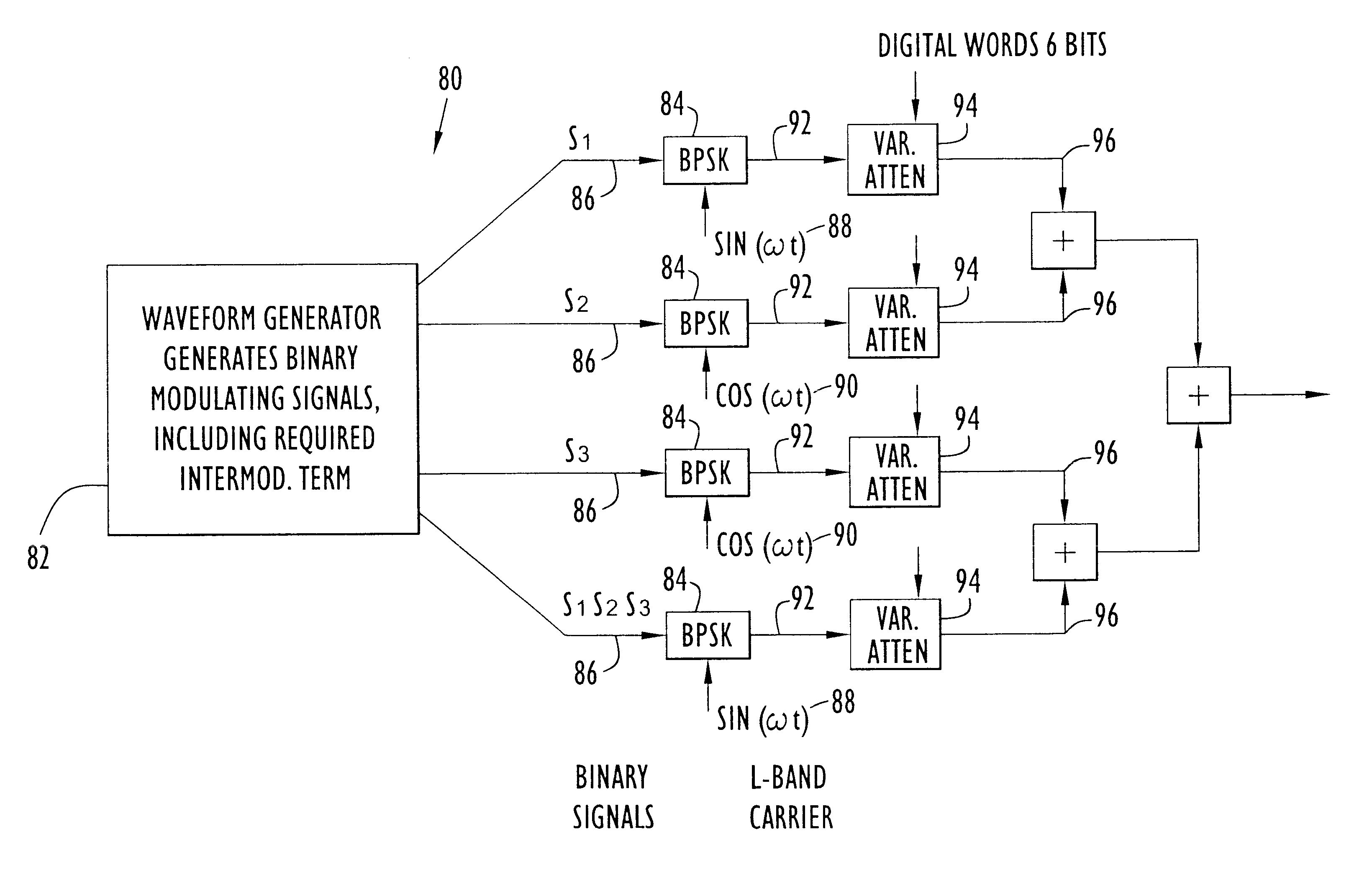
The present invention utilizes a unique architecture wherein modulating signals are generated using a waveform generator and are then used to directly modulate an L-Band Rf carrier. This approach eliminates all of the limitations of these previous approaches. The modulating signal has a much lower frequency content than the modulated If signal, and the processing required to generate the modulating signal is well within the capabilities of space-qualified processors readily available today. In this new architecture, the modulating signals from the waveform generator are clocked binary signals that are sent directly to the modulators, thereby eliminating the D / A converter and any associated jitter and phase noise. Further, because there is no upconversion of the modulated signal required, there is no amplitude variation introduced by bandpass filters.

The operation of this invention depends upon the interplex modulation technique, which has been documented, for example in Ananda, M., ...


PUM


Abstract

A method for generating a global positioning signal from a space based craft including the steps of generating a plurality of binary modulating signals using a waveform generator; separately modulating an in-phase component of a desired carrier of the global positioning signal to be generated with at least a first binary, modulating signal selected from the plurality to generate at least one corresponding in-phase modulated signal component; separately modulating a quadrature component of the carrier with at least a second binary modulating signal selected from the plurality to generate at least one corresponding quadrature modulated signal component; and, combining the at least one in-phase modulated signal component and the at least one quadrature modulated signal component to generate the global positioning signal; wherein the global positioning signal has a constant envelope.

Description

This invention relates to Global Positioning Systems (G.P.S.'s) and more particularly to a programmable waveform generator therefore.BACKGROUND OF INVENTIONAs is well known in the art, the Global Positioning System (G.P.S.) includes 24 satellites orbiting the Earth in six orbit planes, each being inclined with respect to equatorial plane by 55.degree. and longitudinally offset from each other by 60.degree.. It should be recognized that the present method is equally applicable for other positioning systems as well, such as GLONASS for example, wherein 24 satellites (21 operational and 3 spares) are inclined at 65.degree. angles and offset by 120.degree..In G.P.S. each satellite broadcasts carrier signals on the same frequencies. Navigational data is spread by a clear acquisition (C / A) code and modulated on the L1 (1575.42 MHZ) in-phase channel. The navigational data is further spread by a P(Y) code and modulated on both the L1 quadrature and L2 (1227.60 MHZ) in-phase channels.As is w...

Claims


Application Information

Patent Timeline
Patent Type & Authority Patents(United States)
IPC IPC(8): G01S1/00H04L27/34H04L27/36G01S19/02
CPCH04L27/362G01S19/02
Inventor CANGIANI, GENE L.RAJAN, JOHN A.
Owner HARRIS CORP
Why Eureka
Try Eureka