Automatic door assembly and door operator therefor

a technology of automatic door assembly and operator, which is applied in the direction of wing openers, door/window fittings, constructions, etc., can solve the problems of inability to function in a "non-handed" manner, inability to change directions, and normal use of motors to return the door

Inactive Publication Date: 2002-01-08
STANLEY WORKS THE
View PDF36 Cites 66 Cited by
  • Summary
  • Abstract
  • Description
  • Claims
  • Application Information

AI Technical Summary

Problems solved by technology

In this situation, the door panel may not be spring returned from breakout back to its closed position because the spring arrangements inside many prior art operators are not capable of providing this spring returned movement.
In most situations, the motor normally cannot be used to return the door because many building codes require that power to the motor be cutoff after breakout has occurred.
Another problem with most known swing door operators is their inability to function in a "non-handed" manner.
The problem with these operators is that the spring only functions to provide door movement in one direction.
This arrangement, however, is problematic because of the potential for confusion during installation

Method used


Image

  • Automatic door assembly and door operator therefor
  • Automatic door assembly and door operator therefor
  • Automatic door assembly and door operator therefor

Examples


Embodiment Construction

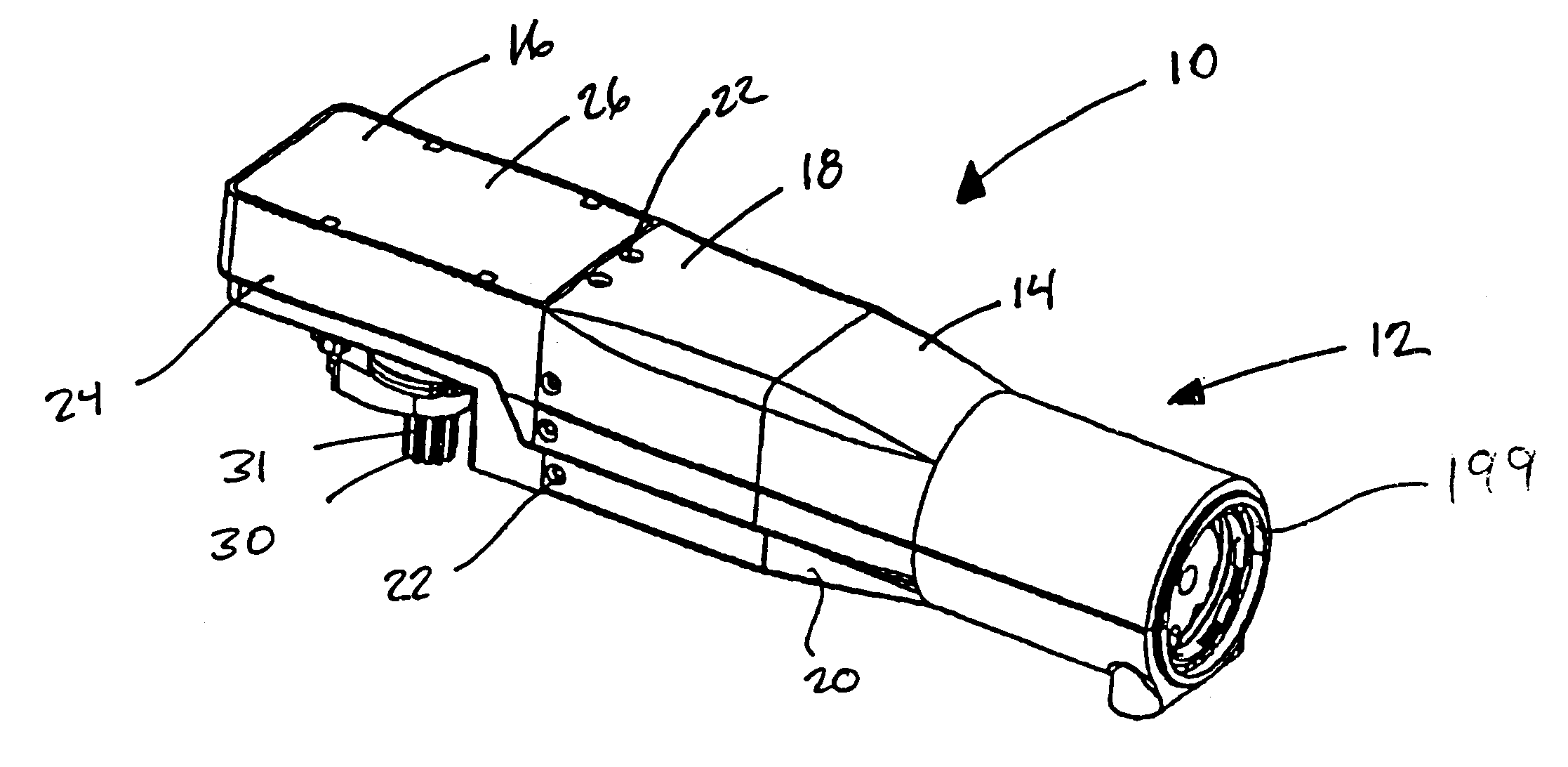
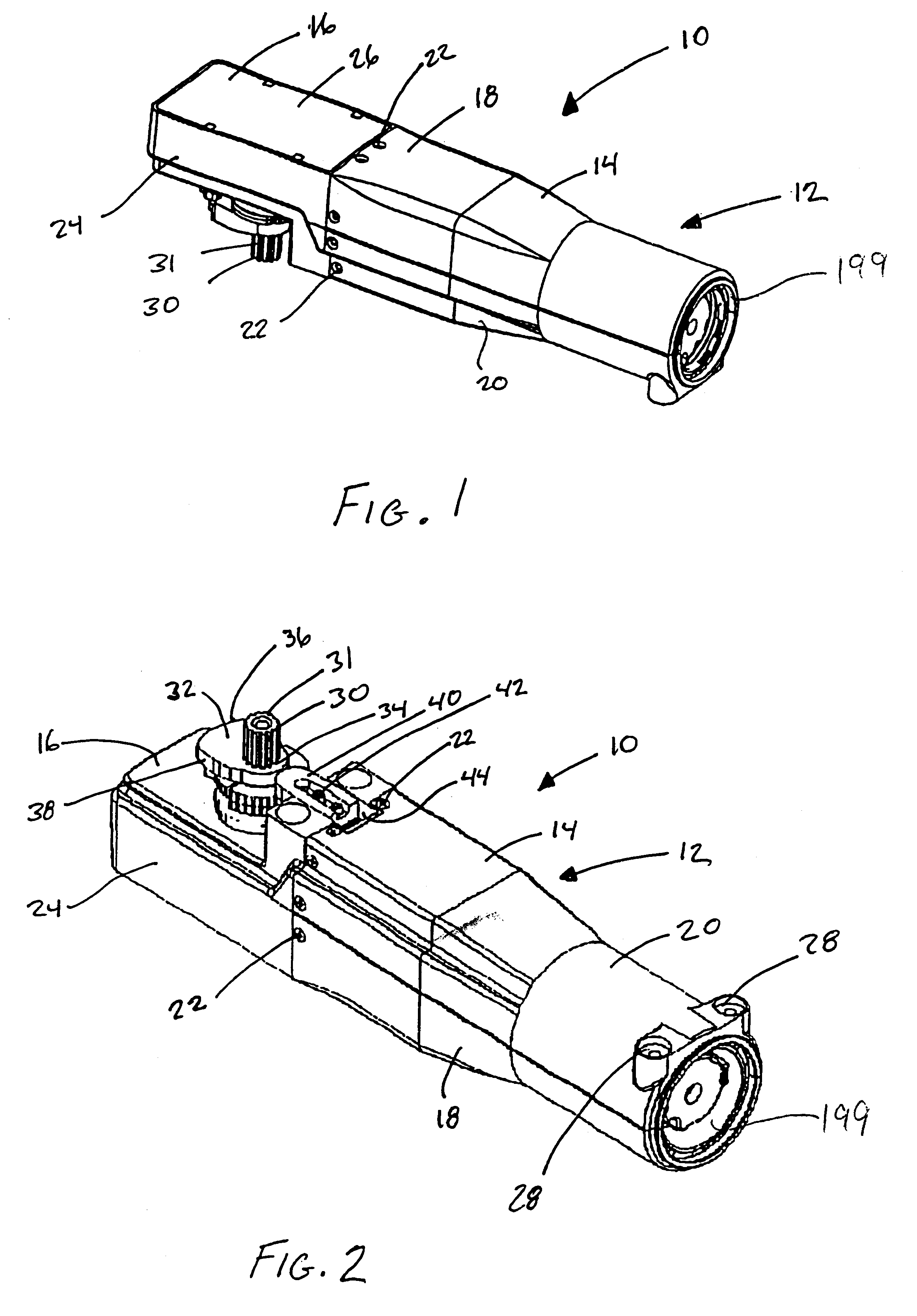
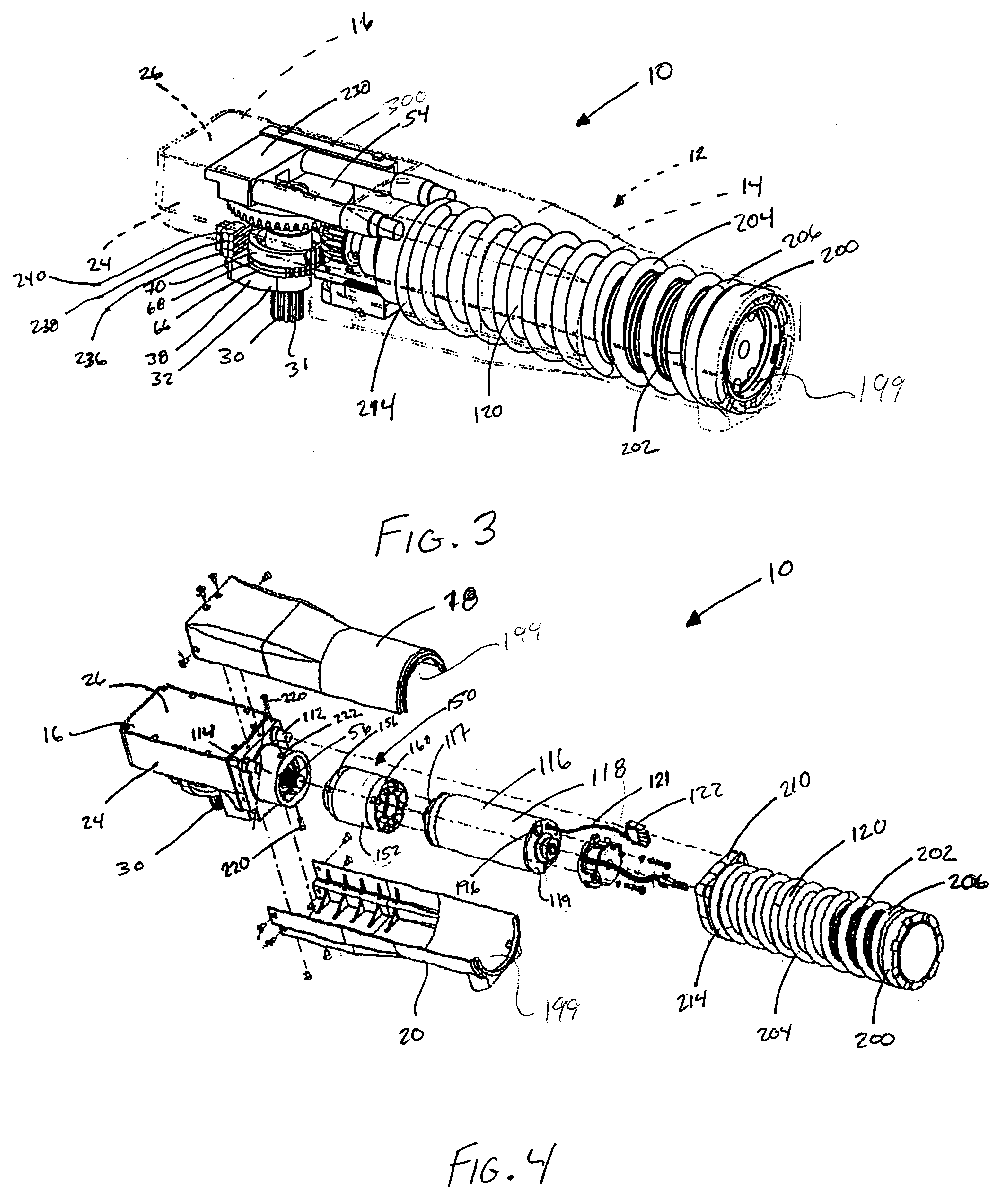
FIG. 1 shows a perspective view of a swing door operator, generally indicated at 10, constructed in accordance with the principles of the present invention, the perspective being taken from above the operator. FIG. 2 shows a perspective view taken from below the operator 10. The operator 10 has a stamped, metal outer casing, or housing generally indicated at 12, comprising a motor / reduction transmission housing portion, generally indicated at 14, and an output drive assembly housing portion, generally indicated at 16. The motor / reduction transmission housing portion 14 has upper and lower housing halves 18, 20, respectively, that are each secured together to a rearward end portion of the output drive assembly housing portion 16 by a plurality of threaded fasteners 22, such as conventional bolts or screws. The construction of the upper and lower housing halves 18, 20 and the manner in which they are secured to the output drive assembly housing portion 16 can be best appreciated from ...


PUM


Abstract

The present application discloses automatic door assemblies and swing operators therefor. One aspect of the disclosure provides a swing door operator that has spring return breakout and from motor driven opening. Another aspect of the disclosure provides a swing door operator that is non-handed with spring return from either direction. Another aspect of the disclosure provides a swing door operator in which spring force is transmitted to the operator output member via a cam structure.

Description

BACKGROUND AND SUMMARY OF THE VARIOUS ASPECTS OF THE INVENTIONSwing door operators are well-known in the automatic door assembly art for controlling the pivoting movements of pivoting or swing door panels between open and closed positions thereof. In most automatic door assemblies, the door panel is moved under power by the door operator in a normal motor driven door opening direction in response to an input device thereof detecting the presence of a person or object adjacent to the door assembly. During this opening movement, energy is stored within a spring structure or the like and, after the door panel has stopped moving, the spring structure releases its energy to move the door panel back towards and into its closed position.Most building codes require these automatic door assemblies to enable the door panel to be opened in a "breakout" manner under manual force or pushing to enable persons to exit the building in emergency situations. Depending on the installation of the opera...

Claims


Application Information

Patent Timeline
IPC IPC(8): E05F3/00E05F15/12E05F3/22E05F3/10
CPCE05D15/54E05F3/224E05F1/105E05F15/614E05F2015/631E05F3/104E05F2003/228E05Y2201/214E05Y2201/232E05Y2201/41E05Y2201/422E05Y2201/434E05Y2400/334E05Y2600/454E05Y2800/113E05Y2800/25E05Y2800/746E05Y2900/132E05Y2201/71E05Y2800/72E05F15/63E05D2015/482E05Y2800/174
Inventor KOWALCZYK, THOMAS M.HASS, BRIAN D.
Owner STANLEY WORKS THE
Why Eureka
Try Eureka