Shielded multiconductor cable and manufacturing method therefor

Inactive Publication Date: 2002-01-08
KOAKKUS
View PDF24 Cites 2 Cited by
  • Summary
  • Abstract
  • Description
  • Claims
  • Application Information

AI Technical Summary

Problems solved by technology

In practice, however, since the two conductive cores A.sub.1 and A.sub.2 are both disposed at positions off the center axis of the insulator rod F, it is difficult to prepare the insulator-covered wire G of the abovementioned construction in which the two conductive cores A.sub.1 and A.sub.2 embedded side by side in the insulator rod F are exactly symmetrical over the entire length thereof in respect of the plane containing the cen...

Method used


Image

  • Shielded multiconductor cable and manufacturing method therefor
  • Shielded multiconductor cable and manufacturing method therefor
  • Shielded multiconductor cable and manufacturing method therefor

Examples


first embodiment

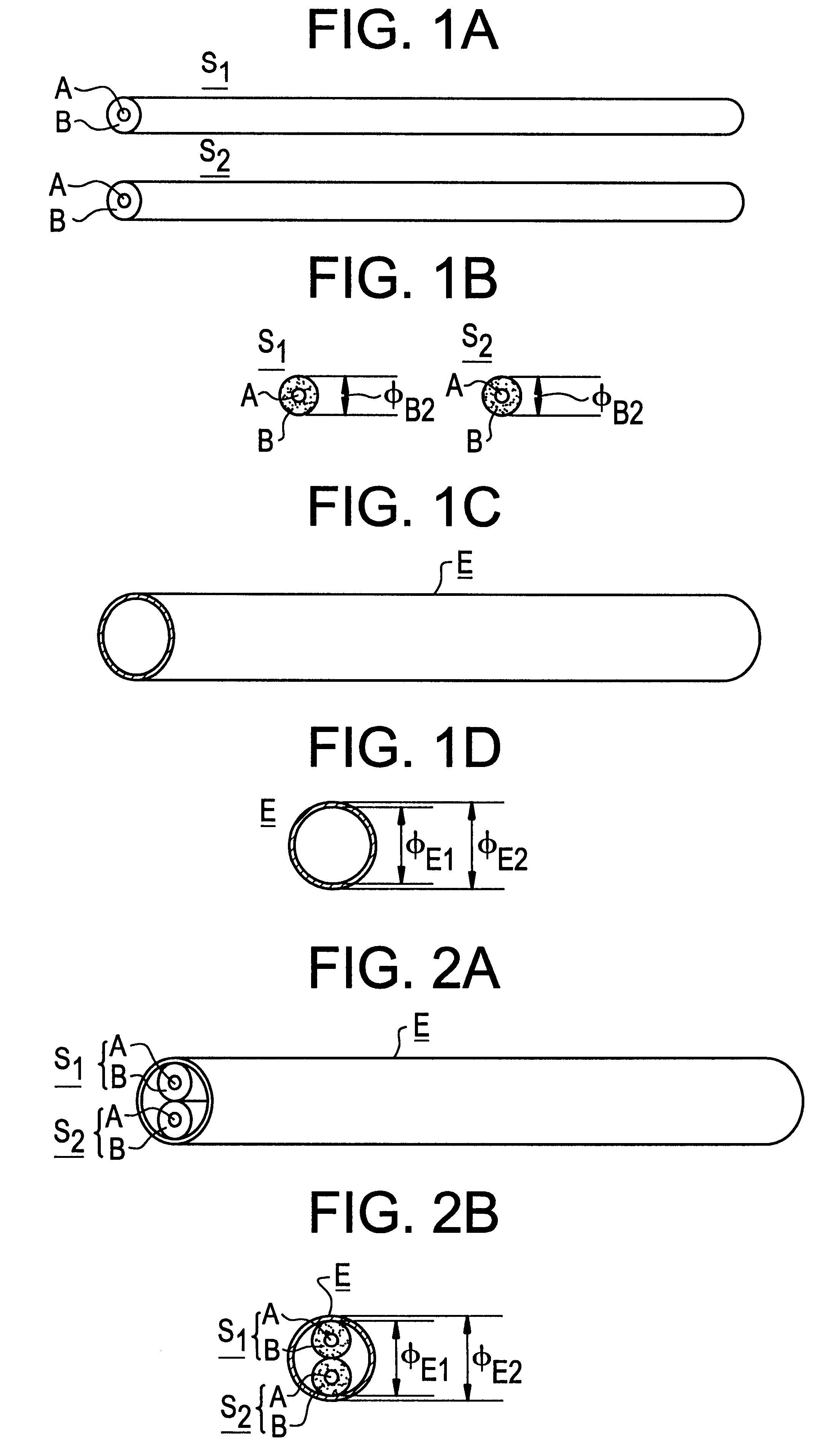
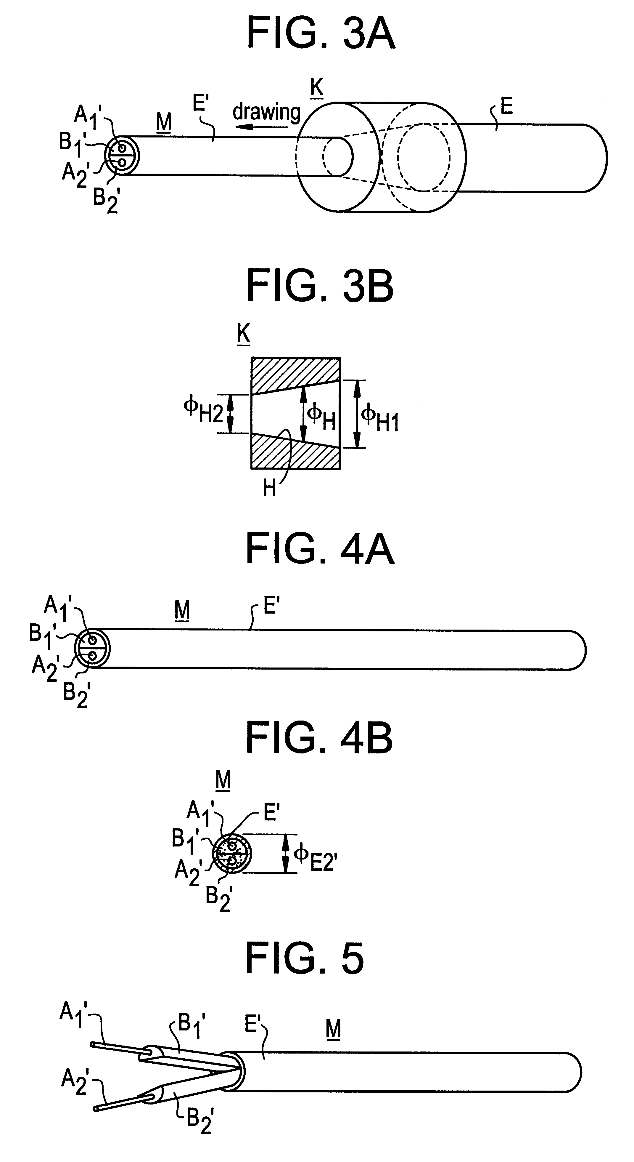
the shielded multi-core cable manufacturing method according to the present invention, depicted in FIGS. 1 through 4, involves the sequence of steps described below.

The first step is to prepare plural, for example, two insulator-covered wires S (which are denoted by S.sub.1 and S.sub.2) each of which has, for example, a circularly-sectioned conductive core A embedded in a cylindrical insulator rod B having an outer diameter .phi..sub.B2 in a manner to be concentric therewith (FIGS. 1A and B), and a cylindrical conductive pipe E which has an inner diameter .phi..sub.E1 large enough to receive the two insulator-covered wires S.sub.1 and S.sub.2 (FIGS. 1C and D). In this case, the inner diameter .phi..sub.E1 of the conductive pipe E is nearly equal to or larger than the twice (2.multidot..phi..sub.B2) of the outer diameter .phi..sub.B2 of each cylindrical insulator rod B having embedded therein one of the insulator-covered wires S.sub.1 and S.sub.2.

Then, the two insulator-covered wires...

second embodiment

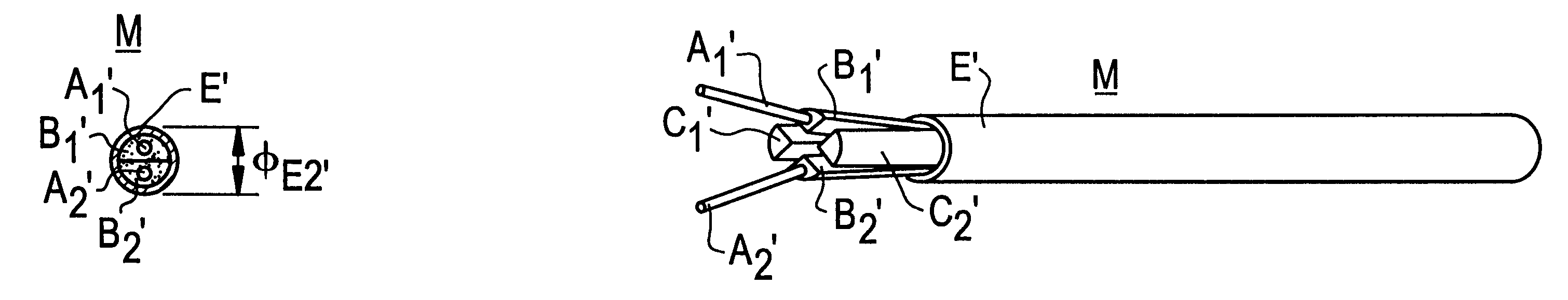
Next, a description will be given, with reference to FIGS. 6 to 9, a shielded multi-core cable and its manufacturing method according to the present invention.

The parts corresponding to those in FIGS. 1 through 4 are marked with the same reference numerals as in the latter.

The shielded multi-core cable manufacturing method according to the second embodiment of the present invention, depicted in FIGS. 6 to 9, involves the sequence of steps described below.

The first step is to prepare: plural for example, two insulator-covered wires S (which are denoted by S.sub.1 and S.sub.2) (FIGS. 6A and B) each of which has, for example, a circularly-sectioned conductive core A embedded in a cylindrical insulator rod B having an outer diameter .phi..sub.B2 in a manner to be concentric therewith (FIGS. 1A and B) as in the first embodiment of the manufacturing method shown in FIGS. 1 to 4; two cylindrical insulator rods C (which are denoted by C.sub.1 and C.sub.2) (FIGS. 6C and D) each of which has ...

third embodiment

A description will be given, with reference to FIGS. 11 to 14, of a shielded multi-core cable and its manufacturing method according to the present invention.

In FIGS. 11 to 14 the parts corresponding to those in FIGS. 1 through 4 are marked with the same reference numerals as in the latter.

The shielded multi-core cable manufacturing method according to the third embodiment of the present invention, depicted in FIGS. 6 to 9, involves the sequence of steps described below.

The first step is to prepare: plural, for example, two insulator-covered wires S (which are denoted by S.sub.1 and S.sub.2) (FIGS. 11A and B) each of which has, for example, a circularly-sectioned conductive core A embedded in a cylindrical insulator rod B having an outer diameter .phi..sub.B2 in a manner to be concentric therewith as in the first embodiment of the manufacturing method shown in FIGS. 1 to 4; a cylindrical insulating tube Q (FIGS. 11C and D) having an inner diameter .phi..sub.Q1 large enough to receiv...


PUM


Abstract

The present invention has a shielded multi-core cable manufacturing method which involves a step of drawing a cylindrical conductive pipe having inserted therein (a) two first cylindrical insulator rods in each of which a conductive core is embedded concentrically therewith, (b) two second cylindrical insulator rod, and/or (c) a cylindrical insulating tube thereby obtaining the shielded multi-core cable which has a construction in which (a) two first insulator rods each having embedded therein one of two conductive cores, (b) two second insulator rods and/or (c) second insulating tube, are held in cylindrical shielding conductive pipe.

Description

The present invention relates to a shielded multi-core cable in which a plurality of insulator rods each having embedded therein one of a plurality of conductive cores, are tightly received in a cylindrical shielding conductive pipe so that the conductive cores are ;held therein around the center axis thereof, and the invention also pertains to a method of making such a shielded multi-core cable.DESCRIPTION OF THE RELATED ARTA conventional shielded multi-core cable and its manufacturing method will be described with reference to FIGS. 21 through 24; the manufacturing method involves a sequence of steps described below.The manufacture begins with the preparation of an insulator-covered wire G which has plural, for example, two conductive cores A.sub.1 and A.sub.2 circular in cross-section, for instance, and embedded side by side in a cylindrical insulator rod F at equal angles around the center axis thereof (FIGS. 21A and B), and a cylindrical conductive pipe E which has an inner dia...

Claims


Application Information

Patent Timeline
IPC IPC(8): H01B13/22H01B13/00H01B7/16H01B7/17H01B7/20H01B11/06
CPCH01B7/16H01B13/224H01B13/0006
Inventor AOSAKI, YASUHISA
Owner KOAKKUS
Why Eureka
Try Eureka