Multi-core cable detecting device and method thereof

A technology for multi-core cables and detection devices, applied in measurement devices, semiconductor/solid-state device testing/measurement, circuits, etc., can solve the problems of increasing the complexity and cost of detection devices, achieve simple structure, improve labor efficiency, and save labor Effect

Active Publication Date: 2008-07-16
BEIJING NAURA MICROELECTRONICS EQUIP CO LTD
View PDF0 Cites 15 Cited by
  • Summary
  • Abstract
  • Description
  • Claims
  • Application Information

AI Technical Summary

Problems solved by technology

The advantage of this method is that it has a high degree of intelligence and is relatively simple to operate, but because more processing components are used, it also increases the complexity and cost of the detection device.

Method used


Image

  • Multi-core cable detecting device and method thereof

Examples


Embodiment Construction

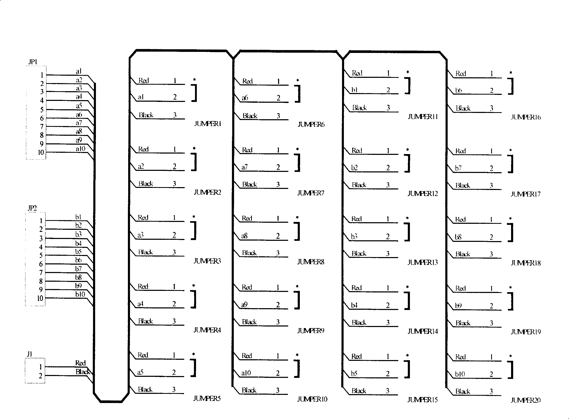
[0025] The multi-core cable detection device of the present invention, its preferred embodiment is as follows figure 1 As shown, it includes the front terminal JP1, the rear terminal JP2 and the test lead terminal J1.

[0026] The front connection terminal JP1 and the rear connection terminal JP2 respectively include a plurality of connection ports. It can include 10 to 20 wiring ports, or more, generally 10, 15, and 20 ports are preferred. In specific applications, it is best to correspond to the number of cores of the corresponding multi-core cable.

[0027] figure 1 The front connection terminal JP1 shown in includes 10 connection ports, which are the first to tenth front connection ports a1, a2, a3, a4, a5, a6, a7, a8, a9, a10; the rear connection terminal JP2 includes 10 The first to tenth rear wiring ports are respectively b1, b2, b3, b4, b5, b6, b7, b8, b9, b10. Up to 10-core cables can be tested. The structure of the plurality of connection ports can be made into ...


PUM


Abstract

The invention discloses a device and a method for detecting a multi-core cable, and the device comprises a front wire-connecting terminator, a back wire-connecting terminator, an electroprobe wire-connecting terminator and a plurality of three-level jumper switches. By selecting the connecting states of the three-level jumper switches and cooperating with a multimeter, the invention can implement the detection of the connected state of a multi-core cable which includes the detection of the correct wiring, wrong wiring and connected states, as well as the detection of the short-connected state between centre yarns in the production, installation, debug and inspection process of the equipment of semiconductor technologies and production lines, etc. The invention has simple structure, convenient using and low cost, and can lead the multi-core cable detection to be implemented by a single person, thus saving labor force and improving labor efficiency.

Description

technical field [0001] The invention relates to a detection device and a detection method, in particular to a device and a method for detecting the connection state of a multi-core cable. Background technique [0002] In many equipment manufacturing such as semiconductor process equipment and production line equipment, the equipment itself requires a large number of connecting cables. After the welding of these large numbers of cables is completed, they need to be inspected to ensure that the cables are correctly connected according to the connection schematic diagram, including whether they are connected and whether there is a short circuit. If the connection state of the cable itself is not checked carefully, the cable will not be connected correctly according to the design due to welding errors, which will cause great trouble to the debugging of the equipment. In addition, during the debugging and maintenance of equipment, it is often necessary to check the status of the...

Claims


Application Information

Patent Timeline
Patent Type & Authority Applications(China)
IPC IPC(8): G01R31/02G01R31/08H01L21/00H01L21/66
Inventor 张俊
Owner BEIJING NAURA MICROELECTRONICS EQUIP CO LTD
Why Eureka
Try Eureka