

Multi-core cable and aligning method therefor
a multi-core cable and alignment method technology, applied in the direction of cables, insulated conductors, coupling device connections, etc., can solve the problem of short exposed length of electronic wires from multi-core cables, and achieve the effect of reducing the exposed length of electronic wires and facilitating attachmen
- Summary
- Abstract
- Description
- Claims
- Application Information
AI Technical Summary
Benefits of technology
Problems solved by technology
Method used
Image

Examples
Embodiment Construction
[0064]An example of an embodiment of an aligning method for a multi-core cable according to the invention will hereinafter be described with reference to the drawings. The multi-core cable can adopt various modes such as the case of connecting both end sides to a substrate or the case of connecting only one end side to a substrate and attaching the other end side to a connector, and in the following multi-core cable, a configuration of one end side will be described.
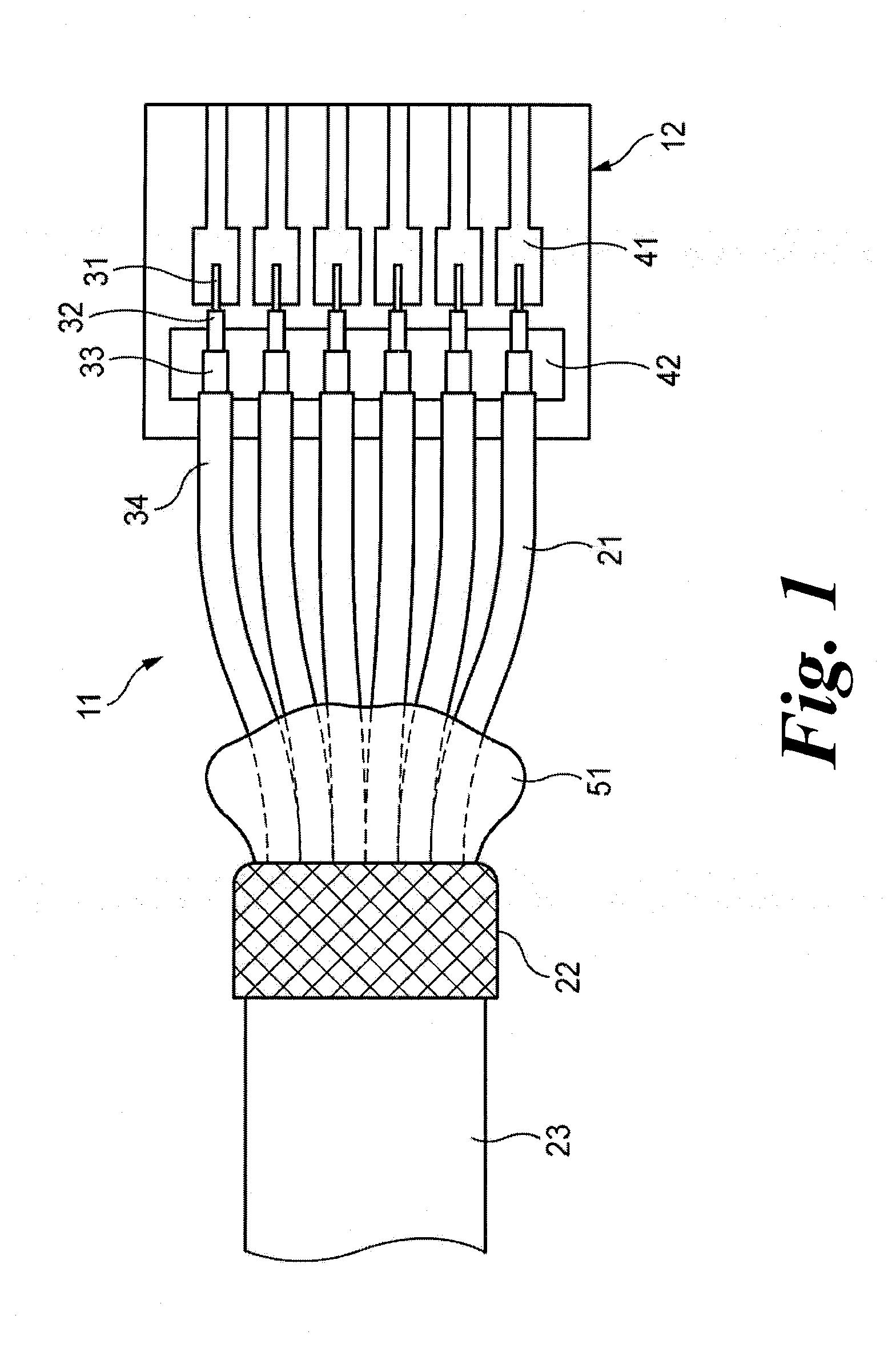
[0065]As shown in FIG. 1, a multi-core cable 11 is a cable used in connection between, for example, medical devices or information devices, and the end of the multi-core cable is connected to a connector or a substrate 12 arranged inside a probe.
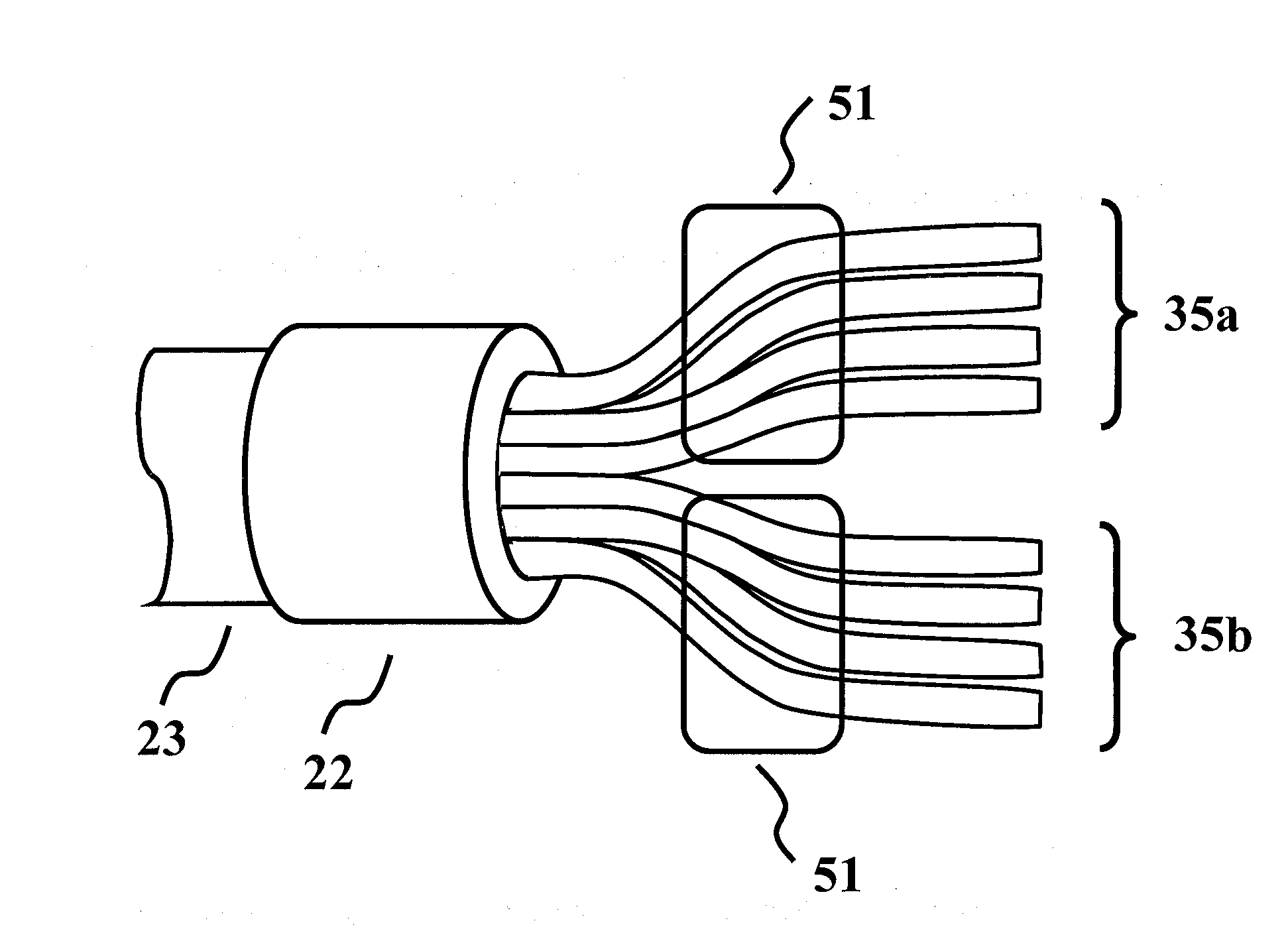
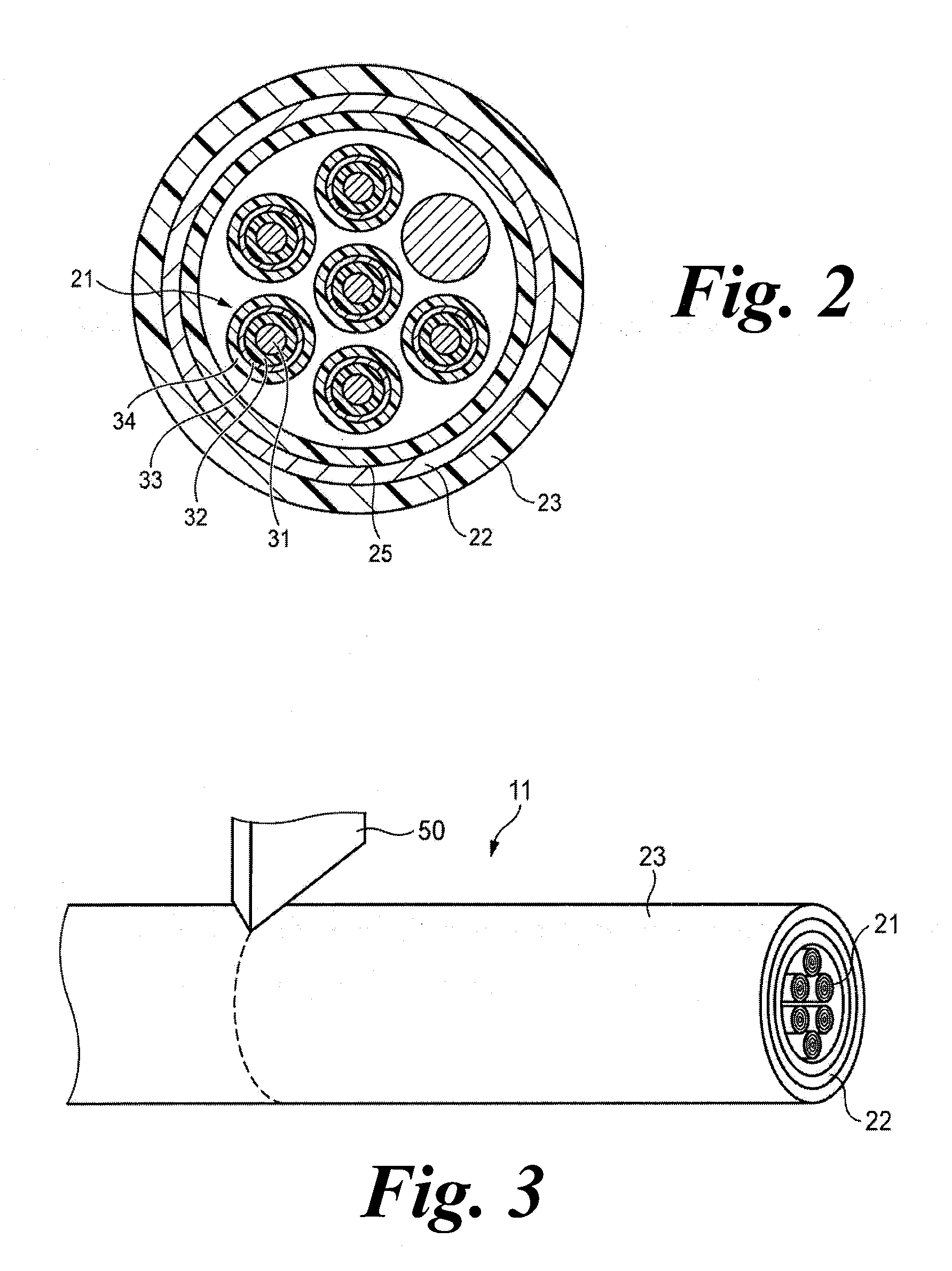
[0066]As shown in FIG. 2, plural coaxial cables (electronic wires) 21 are bundled inside the multi-core cable 11. The periphery of these plural coaxial cables 21 has a shield layer (overall shield) 22 in which copper alloy wires are braided in order to ensure shielding and obtain...
PUM
| Property | Measurement | Unit |
|---|---|---|
| distance | aaaaa | aaaaa |
| length | aaaaa | aaaaa |
| length | aaaaa | aaaaa |
Abstract
Description
Claims
Application Information