Non-uniformly-rigid barrier wall spacers used to correct problems caused by thermal contraction of smectic liquid crystal material

Inactive Publication Date: 2002-01-08
DENSO CORP
View PDF10 Cites 399 Cited by
  • Summary
  • Abstract
  • Description
  • Claims
  • Application Information

AI Technical Summary

Benefits of technology

To solve the problems thus far described, the present invention has a first object to provid

Problems solved by technology

When the liquid crystal cell is made of a smectic liquid crystal, however, if an orientation defect in the smectic liquid crystal or a disturbance in the liquid crystal layer structure is caused by a local pressure or impact from the outside, its orientation state is not restored even after releasing the local pressure or impact.
On the other hand, when the liquid crystal cell is made of a smectic liquid crystal, an orientation disturbance or a defect is likely to occur in the smectic liquid crystal at the periphery of the spherical spacer, and the display characteristics of the liq

Method used


Image

  • Non-uniformly-rigid barrier wall spacers used to correct problems caused by thermal contraction of smectic liquid crystal material
  • Non-uniformly-rigid barrier wall spacers used to correct problems caused by thermal contraction of smectic liquid crystal material
  • Non-uniformly-rigid barrier wall spacers used to correct problems caused by thermal contraction of smectic liquid crystal material

Examples


first embodiment

[First Embodiment]

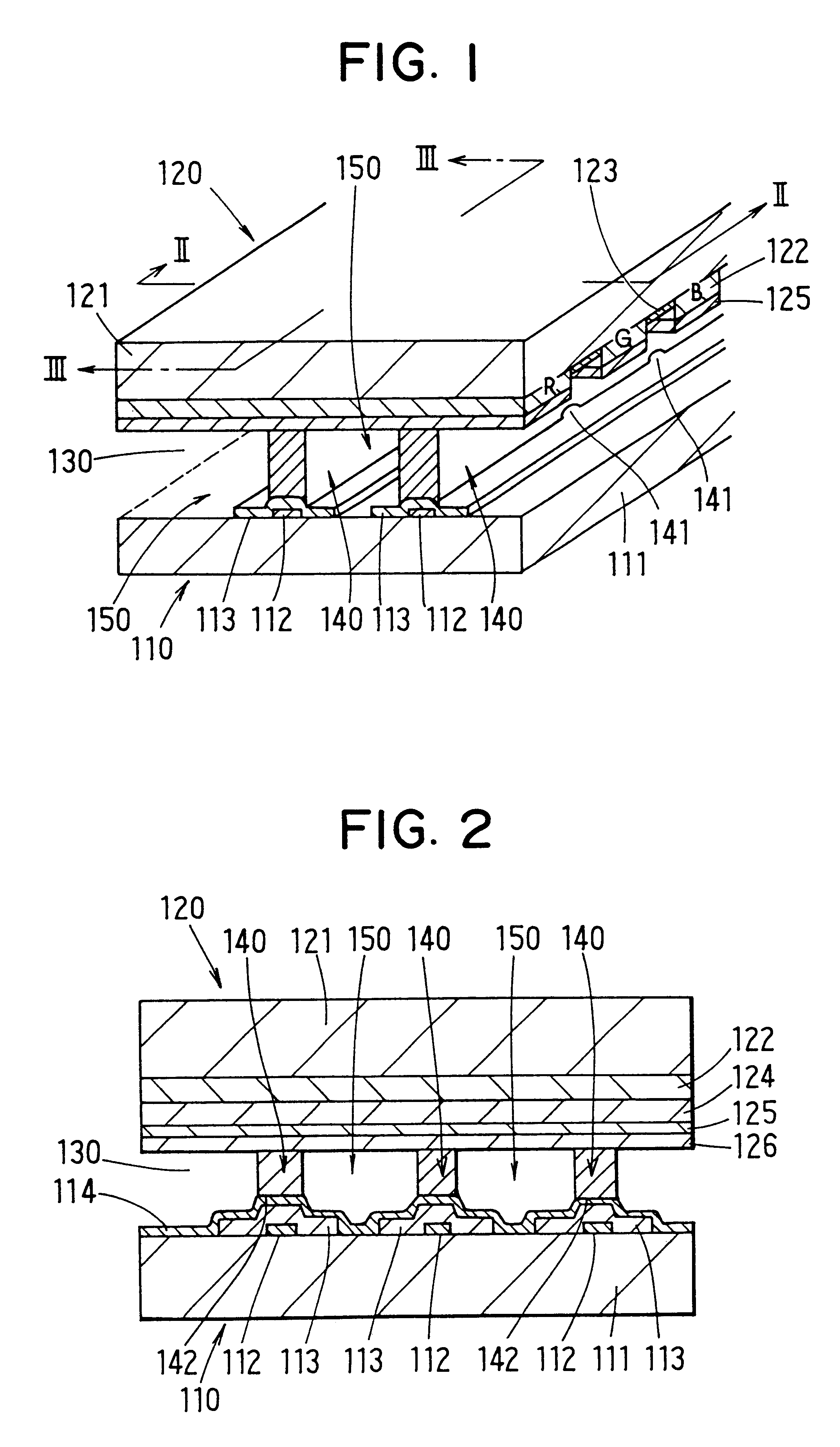
A first embodiment of the present invention will be described with reference to FIGS. 1 to 7.

FIGS. 1 to 3 show a first embodiment of a liquid crystal cell according to the present invention.

The liquid crystal cell is provided with a lower electrode substrate 110 and an upper electrode substrate 120, between which a smectic liquid crystal 130 is disposed together with a plurality of barrier walls 140 on the inner side of a band seal 120a (as referred to FIG. 7). Here, the smectic liquid crystal 130 is exemplified by a ferroelectric liquid crystal (FLC) or an anti-ferroelectric liquid crystal (AFLC). On the other hand, the smectic liquid crystal 130 may be replaced by a liquid crystal having similar viscosity characteristics such as a liquid crystal having a high viscosity at the room temperature.

The lower electrode substrate 110 is constructed by forming a plurality of metal electrodes 112, a plurality of transparent electrodes 113 and an orientation film 114 in thi...

second embodiment

[Second Embodiment]

FIG. 8 shows a second embodiment of the liquid crystal cell according to the present invention.

In this second embodiment, individual through holes 144 are formed in place of the individual through holes 141, as described in connection with the first embodiment, between the upper electrode substrate 120 and the individual barrier walls 140.

Here are formed the individual through holes 144 in the following manner.

When the upper electrode substrate 120 is formed at the upper electrode substrate forming step S102, of the first embodiment, those portions of the orientation film 126 and the over coat layer 124, which correspond to the groove-shaped regions of the two adjoining color filter layers 122, are recessed into the individual groove-shaped regions, as shown in FIG. 8.

Unlike the first embodiment, in this second embodiment, the plurality of barrier walls 140 are formed by a method similar to the aforementioned one on the inner surface of the orientation film 114 of...

third embodiment

[Third Embodiment]

FIGS. 9 and 10 show a third embodiment of the liquid crystal cell according to the present invention.

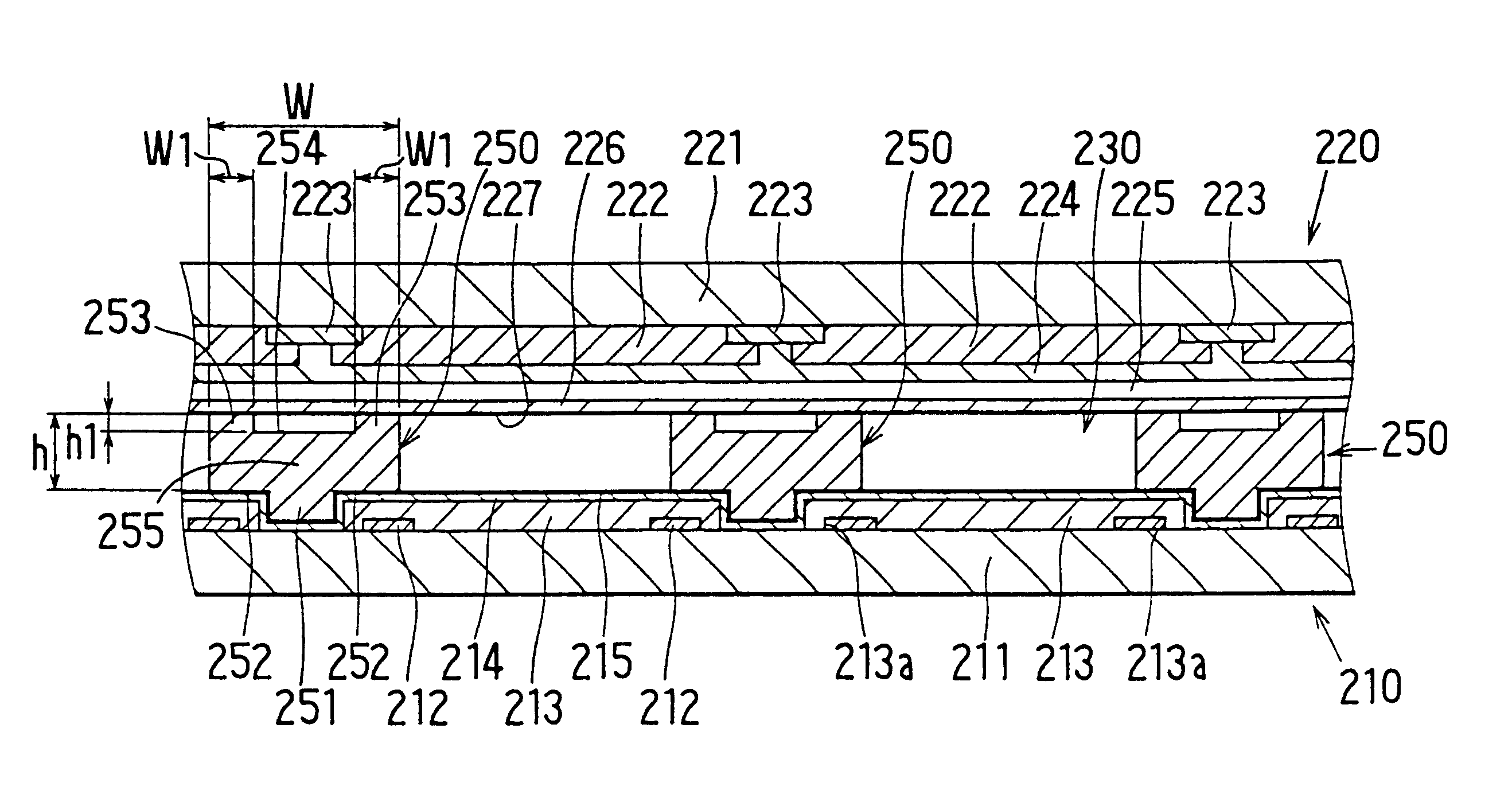
The liquid crystal cell is provided with a lower electrode substrate 210 and an upper electrode substrate 220, between which a smectic liquid crystal 230 is disposed together with a plurality of barrier walls 250 on the inner side of a band seal 240.

Here, the smectic liquid crystal 230 is exemplified by a ferroelectric liquid crystal or an anti-ferroelectric liquid crystal. The smectic liquid crystal 230 may be replaced by a liquid crystal having similar viscosity characteristics such as a liquid crystal having a high viscosity at the room temperature.

The lower electrode substrate 210 is constructed by forming a plurality of auxiliary electrodes 212, a plurality of transparent electrodes 213, a transparent insulating film 214 and a transparent orientation film 215 in this order on the inner surface of a transparent substrate 211 made of a transparent glass sheet.

Her...


PUM


Abstract

According to this liquid crystal cell, a vacuum to be established between two electrode substrates as a result of the volume shrinkage of a liquid crystal having a high viscosity at the room temperature can be damped by communicating between two of a plurality of filling portions formed between two electrode substrates by a plurality of barrier walls through the intervening barrier walls. An anti-ferroelectric liquid crystal (AFLC) is used as the liquid crystal. The liquid crystal cell has a lower electrode substrate and an upper electrode substrate, between which a smectic liquid crystal is disposed together with a plurality of barrier walls on the inner side of a band seal. Each barrier wall has through holes to communicate between the two filling portions located on the two sides of the barrier walls.

Description

This application is based on Japanese Patent Application Nos. Hei. 10-153233 filed on Jun. 2, 1998, Hei. 10-247537 filed on Sep. 1, 1998, and Hei. 10-317983 filed on Nov. 9, 1998, the contents of which are incorporated herein by reference.BACKGROUND OF THE PRESENT INVENTION1. Field of the Present InventionThe present invention relates to a liquid crystal cell to be suitably adopted in a liquid crystal display device or the like, and a process for manufacturing the liquid crystal cell.2. Description of the Related ArtIn recent years, the liquid crystal cell is utilized as a display element for a TV set, a personal computer or a work station, or a display element for a watch, a calculator or a measurement device because it is suited for a light weight and for a thin shape.This display element is caused to transmit, reflect or shade a light mainly by utilizing the shuttering action of the liquid crystal.The liquid crystal to be used in the display element is represented by a nematic li...

Claims


Application Information

Patent Timeline
IPC IPC(8): G02F1/13G02F1/1339G02F1/141
CPCG02F1/13394G02F1/141
Inventor OZAKI, MASAAKIMIYASHITA, KOICHIMAEKAWA, KENJIKANEKO, TAKAHISAMATSUMOTO, NAOKIINOGUCHI, KAZUHIRO
Owner DENSO CORP
Why Eureka
Try Eureka