

Automated design partitioning
a design and automatic technology, applied in the field of electronic design automation and simulation tools, can solve the problems of inability to handle arbitrary partitions, many manual steps to accomplish the necessary re-partitioning, and increasing design complexity and design diversity
- Summary
- Abstract
- Description
- Claims
- Application Information
AI Technical Summary
Problems solved by technology
Method used
Image

Examples
Embodiment Construction
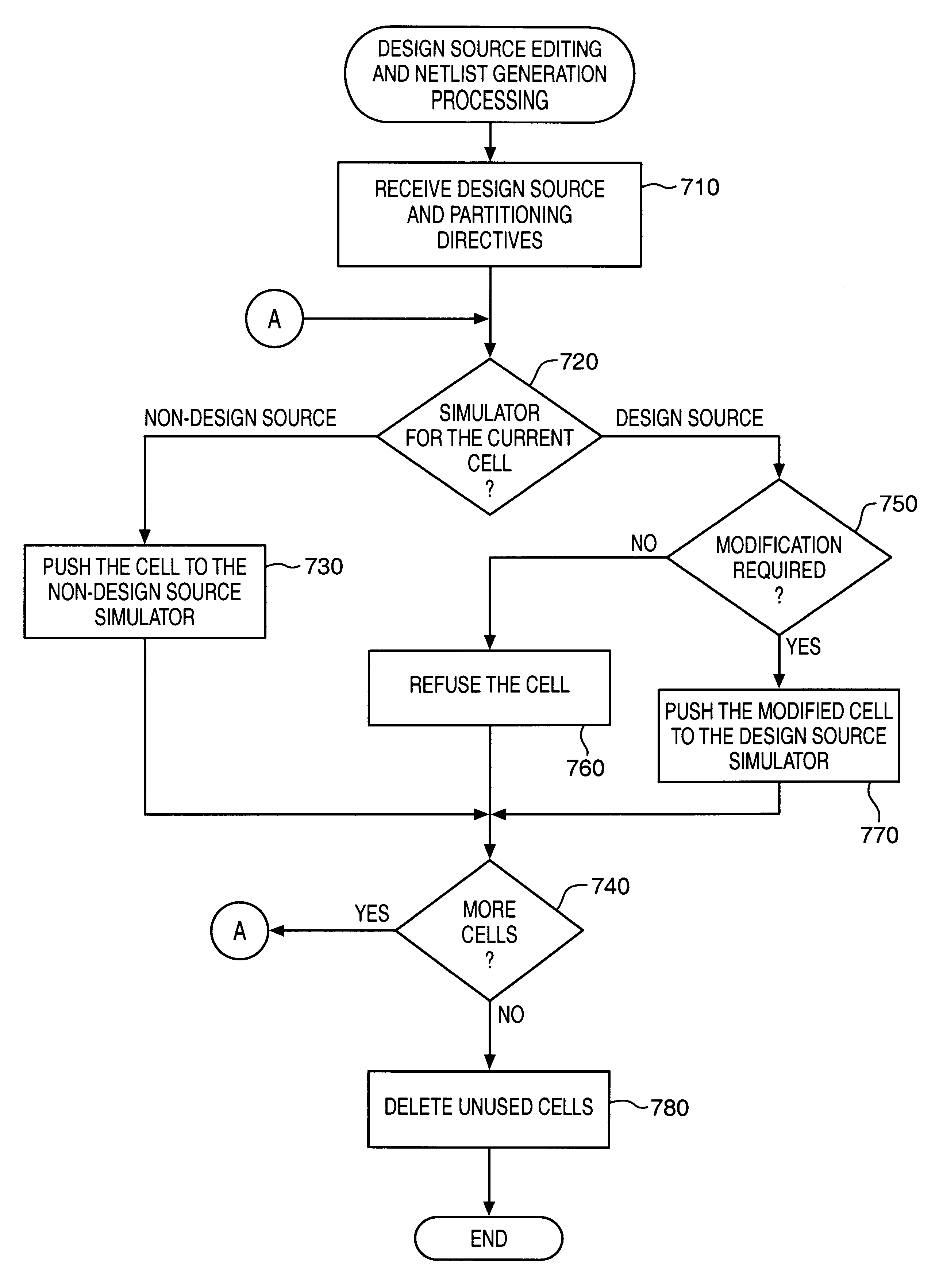
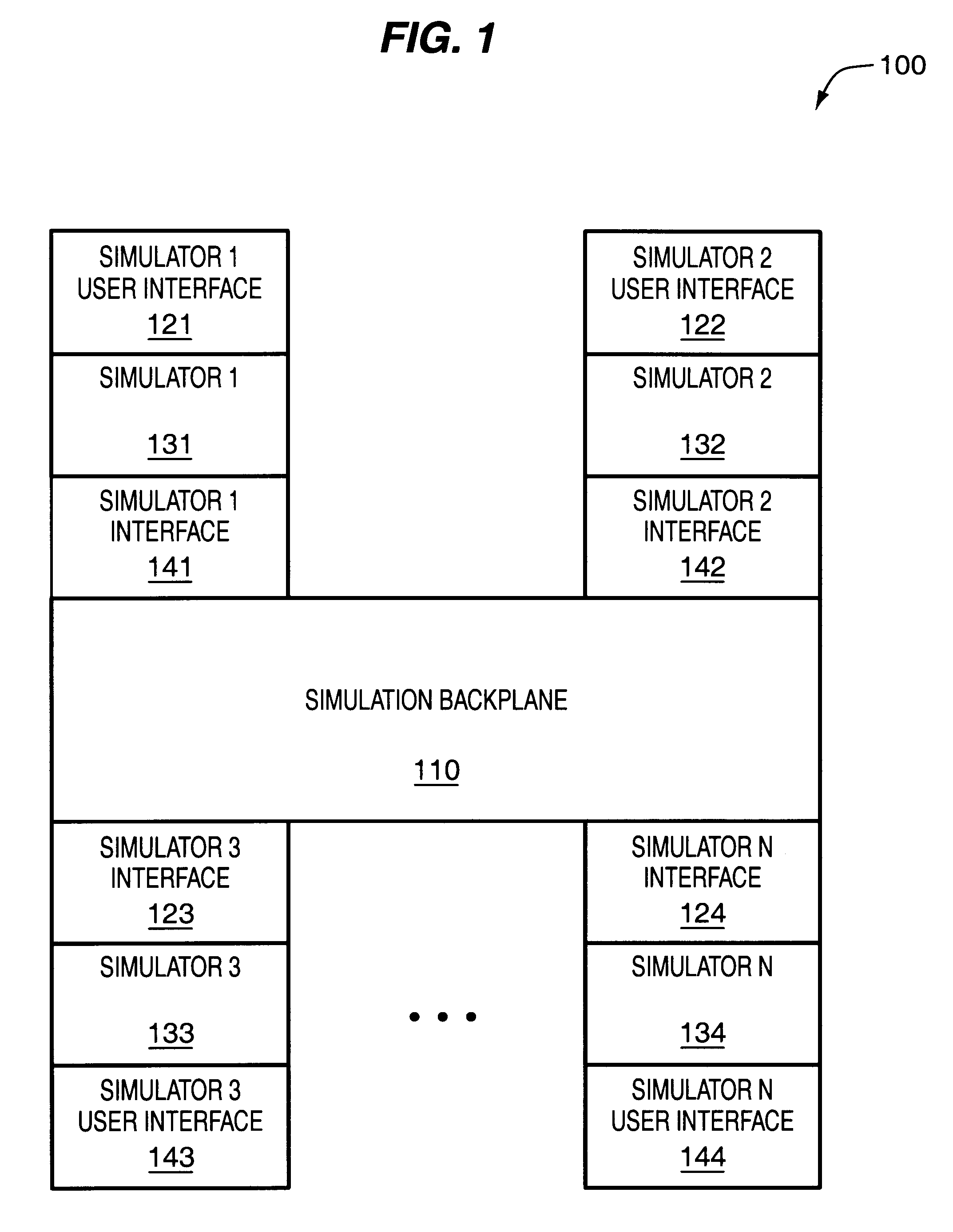
A flexible and extensible automated design partitioning mechanism that facilitates simulation sessions employing multiple simulators is described. According to various embodiments of the present invention, a multi-source hierarchical partitioning system provides a designer with the ability to create customized flows based upon combinations of schematics and hardware description languages (HDLs). Briefly, as one feature of the present invention, a designer may use simple rules to specify which of a plurality of simulators will simulate various parts of a design. In one embodiment, the automated design partitioning mechanism generates hierarchical design representations for all partitions, including those associated with non-design source simulators in order to preserve name space mapping across all simulators. Additionally, the automated design partitioning mechanism permits the user to specify arbitrary partitions thereby allowing various instances of a given cell to be simulated by...
PUM
 Abstract
Description
Claims
Application Information