Branching apparatus

a branching apparatus and branching technology, applied in the direction of coupling device connection, contact member penetrating/cutting insulation/cable strand, substation/switching arrangement details, etc., can solve the problems of large branching space, low operation efficiency, and high cos

Inactive Publication Date: 2002-01-29
YAZAKI CORP
View PDF16 Cites 6 Cited by
  • Summary
  • Abstract
  • Description
  • Claims
  • Application Information

AI Technical Summary

Benefits of technology

In this construction, when expressing the connection between the penetrating connection conductors and the wires in terms of the ratio of the penetrating connection conductors to the wires, (p1:n) or (n:n) is obtained. Therefore, the number of branching connections of the wires can be increased in a small space, and besides the intermediate splice of the branch connection, in which the ratio of the penetrating connection conductors to the wires is (1:n) or (n:n), can be absorbed, and therefore the branching apparatus can be formed into a smaller size as compared with the conventional apparatus, and besides the cost can be reduced.
In this construction, the intermediate connection terminals, each including the wire connecting portions for electrical connection to the wire, and the penetrating connection conductor-connecting portion for passing the associated penetrating connection conductor therethrough in electrically-connected relation thereto, are incorporated in each of the branch connection insulating plates. Therefore, the wires can be easily electrically connected to the penetrating connection conductors at necessary portions thereof. In this electrical connection, the intermediate connection terminals are set respectively in the required positions, and the penetrating connection conductors are supported respectively at the required positions, and the branch portions can be easily changed by changing the set positions of the terminals and the positions of supporting of the conductors.
With this construction, the planes of the connector male terminal portions of the penetrating connection conductors, exposed to the outer surface of the insulating housing, are disposed in a row. When the wires are set to be disposed perpendicularly to the planes of the connector male terminal portions, the planes of those portions of the penetrating connection conductors, passing through the penetrating connection conductor-connection portions of the respective intermediate connection terminals and passing through the branch connection insulating plates, are disposed parallel to the wires. Therefore, the width of each intermediate connection terminal is smaller as compared with the case where the planes of those portions of penetrating connection conductors, passing through branch connection insulating plates, are disposed perpendicularly to wires. As a result, the interval between the intermediate connection terminals is smaller, and therefore the size of the branching apparatus can be further reduced.

Problems solved by technology

However, this branching apparatus 1 has a problem that when expressing the connection between the press-connecting terminals 3 and the wires 4 in terms of the ratio of the terminals 3 to the wires 4, the intermediate splice absorption can be effected only in the ratio (1:1).
Therefore, there have problems that the efficiency of the operation is low, that the cost is high, and that a large branching space is required.

Method used


Image

  • Branching apparatus
  • Branching apparatus
  • Branching apparatus

Examples


first embodiment

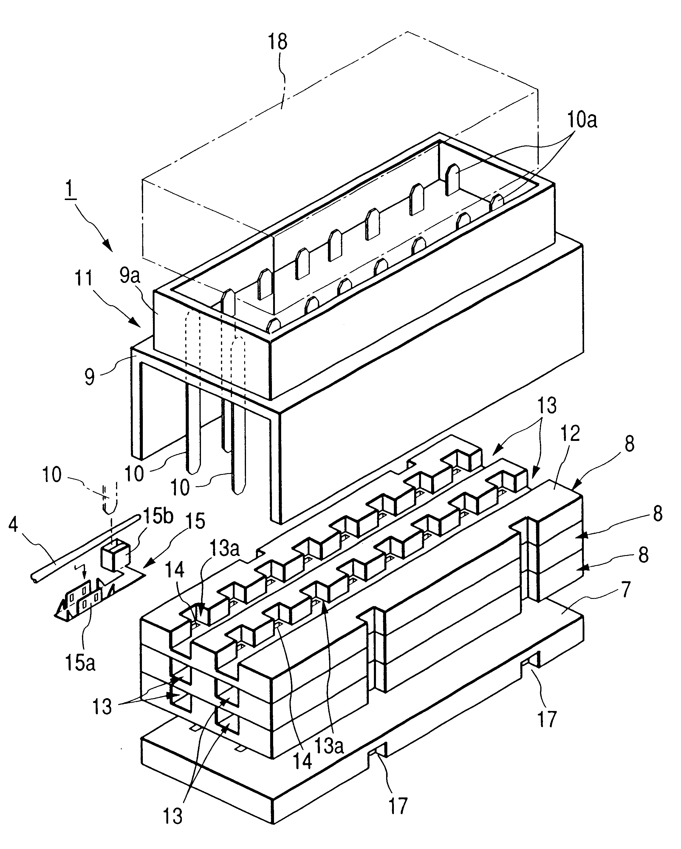
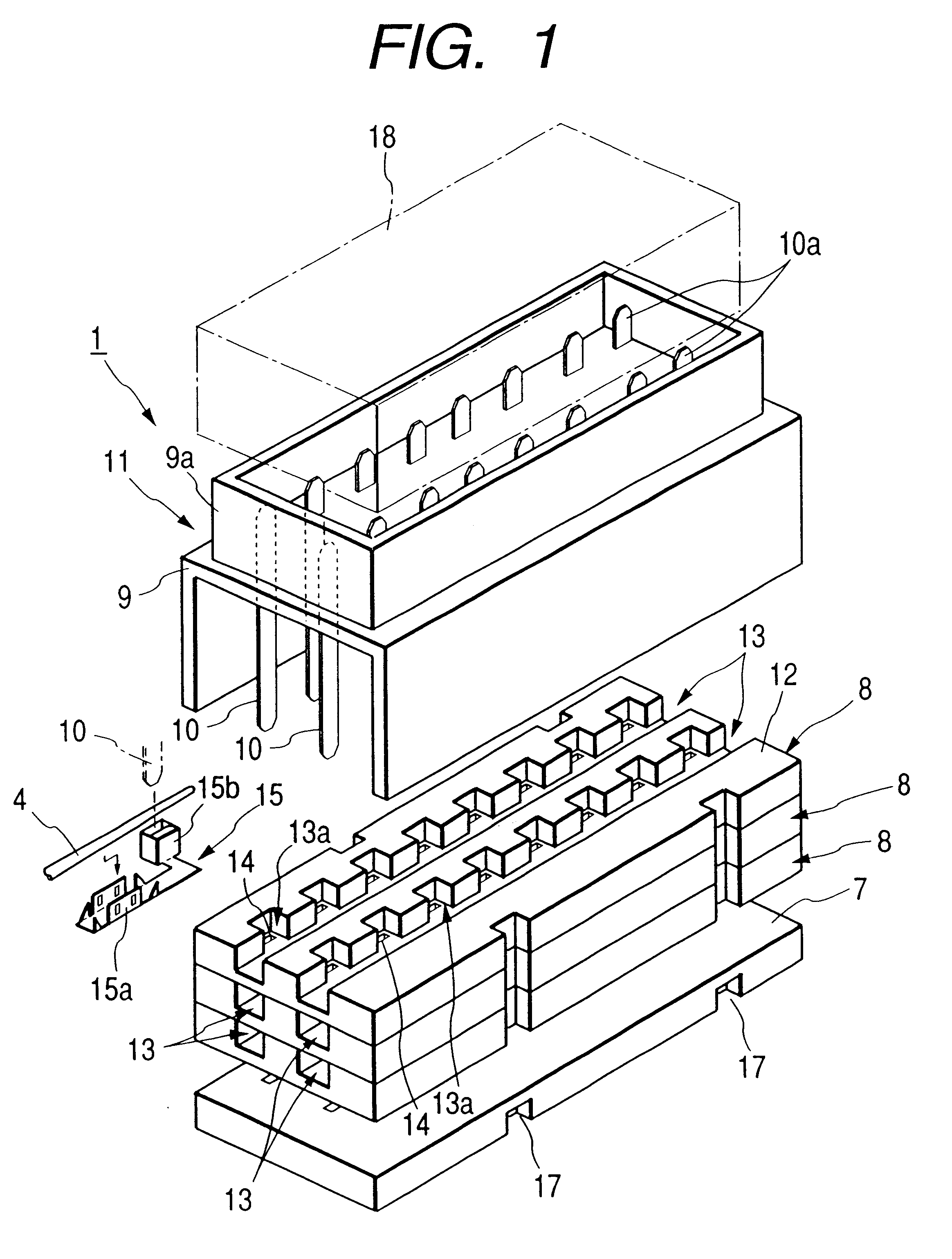
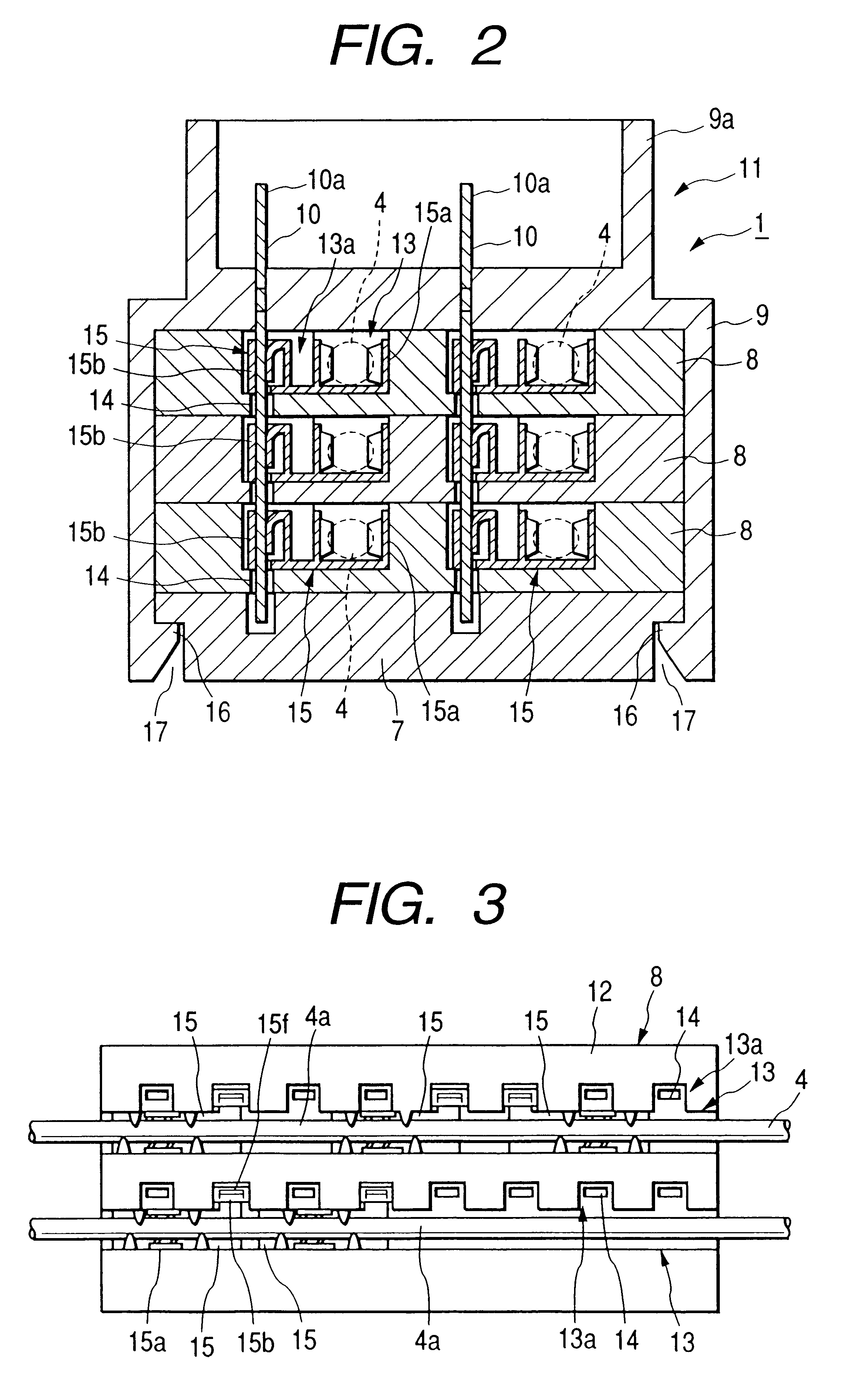
FIGS. 1 to 4 show a branching apparatus of the invention. FIG. 1 is an exploded, perspective view of the branching apparatus of this embodiment. FIG. 2 is a transverse cross-sectional view of the branching apparatus of this embodiment. FIG. 3 is a plan view showing a condition in which wires and intermediate connection terminals are mounted or incorporated in a branch connection insulating plate used in the branching apparatus of this embodiment. FIG. 4 is a perspective view of the intermediate connection terminal used in the branching apparatus of this embodiment.

The branching apparatus 1 of this embodiment includes an insulating bottom plate 7, and a plurality of branch connection insulating plates 8 stacked together on the insulating bottom plate 7. The wires 4 are adapted to pass through each of the branch connection insulating plates 8 in parallel relation to each other. The branching apparatus 1 further includes a branch connector portion 11 which includes an insulating housin...

second embodiment

FIGS. 5A and 5B and FIGS. 6A and 6B show a branching apparatus of the invention. FIGS. 5A and 5B are perspective views of two kinds of penetrating connection conductors 10 used in this embodiment. FIG. 6A is a plan view showing the arrangement of connector male terminal portions 10a of the penetrating connection conductors 10 in the branching apparatus of this embodiment. FIG. 6B is a vertical cross-sectional view showing a condition of connection between each penetrating connection conductor 10 and the corresponding intermediate connection terminal 15 in the branching apparatus 1.

In the branching apparatus 1 of this embodiment, the planes of those portions of the penetrating connection conductors 10 (each including a tab conductor and supported on the insulating housing 9), passing through the branch connection insulating plates 8, are disposed in a direction coinciding with the direction of extending of the wire setting grooves 13 in the branch connection insulating plates 8. Each...


PUM


Abstract

A branching apparatus includes an insulating bottom plate 7, and a plurality of branch connection insulating plates 8 stacked together on the insulating bottom plate 7, and a branch connector portion 11, wires 4 passing through each of the branch connection insulating plates 8 in parallel relation to each other. The branch connector portion 11 includes an insulating housing 9, cooperating with the insulating bottom plate 7 to hold the branch connection insulating plates 8, and a plurality of penetrating connection conductors 10 supported on the insulating housing 9. One end portion of each of the penetrating connection conductors 10 passes through the branch connection insulating plates 8, and is electrically connected to the associated wires 4 to thereby effect the branch connection, and the other end portion of each penetrating connection conductor is exposed to the exterior, and serving as a connector male terminal portion 10a.

Description

1. Technical FieldThis invention relates to a branching apparatus for branching a plurality of juxtaposed wires, and more particularly related to a branching apparatus suitably used in a wire harness for an automobile.2. Related ArtIn a conventional branching apparatus 1 of the type described, rows of press-connecting terminals 3 are provided on one side surface of an insulating housing 2 in a manner that the row is offset from the other row, as shown in FIGS. 8 and 9. A plurality of juxtaposed wires 4 is respectively located in opposed relation to press-connecting grooves that is formed respectively in the press-connecting terminals 3.In this condition, a press-connecting insulating cover 5 is pressed to cover all of the press-connecting terminal 3, and the wires 4 are press-fit into the press-connecting grooves, respectively. Therefore, the wires 4 are electrically connected to the terminals 3, respectively. In this condition, the press-connecting insulating cover 5 is retained on...

Claims


Application Information

Patent Timeline
Patent Type & Authority Patents(United States)
IPC IPC(8): H01R9/03H01R4/24H01R4/00
CPCH01R9/03
Inventor SAKAMOTO, MASAMIMORI, SHIGEKI
Owner YAZAKI CORP
Why Eureka
Try Eureka