As seen from the above description, although both the W / T tire and the T / L tire for truck and bus are used under the same heavy loading condition, a great difference in external force applied to the bead portion during the running under the heavy loading is naturally caused between both the tires.
As the fall quantity increases, it is needless to say that problems with the bead portion are apt to be caused.
Furthermore, with the W / T tire for truck and bus is difficult to attain
automation in the mounting onto the rim, while the T / L tire is made possible to easily assemble on the rim by means of an automatic assembling device.
However, the above conventional means and their extensions become no longer impossible to cope with the present circumstances such as more long-lived tire performance, increase of demand for the formation of a recapped tire after the
tread rubber is worn, severer demands for weight reduction and the like.
Particularly, the increase of the bead portion volume and the additional arrangement of the bead portion reinforcing cord layer are inappropriate for weight reduction.
Furthermore, the excessive volume increase and additional arrangement bring about a greater amount of
heat generation during the running of the tire under the heavy loading and hence the inside of the bead portion becomes a high temperature.
Such a high temperature brings about the rubber deterioration and the adhesion degradation, whereby separation failure is apt to be caused from
cracking at the turnup end portion of the carcass ply or the end portion of the bead portion reinforcing cord layer.
Further, when the tire is used under condition of such a high temperature over a long period, the rationalization of the arrangement and shape of the cord layer with much effort is damaged by a large
creep deformation of rubber as mentioned later and hence the given object can not be attained.
Also, the shape of the carcass line is lost to bring about degradation of the steering stability.
As a result that the above large shearing strain under the inflation of
internal pressure simultaneously acts together with shearing strain produced in the turnup end portion during the running under the heavy loading, a crack is first created at the turnup end portion and grows into the separation failure as the running distance becomes long.
Therefore, even if it is intended to rationalize the aforementioned means for improving the durability of the bead portion, the sufficient bead portion durability can not be realized.
When such a high-temperature state is held over a long period of time, the
creep deformation is caused in rubber.
Although the region of the bead portion other than the composite side-rubber is naturally rendered into a high temperature through
heat generation through
hysteresis loss being a viscoelastic property inherent to rubber based on amplitudes of internal strain and
internal stress produced by the repetition of loading and its release during the running of the tire, the
heat generation produced in the composite side-rubber under a high
contact pressure to the
flange particularly contributes to the occurrence of
creep deformation.
Furthermore, the composite side-rubber located under the high
contact pressure prematurely causes the wearing and finally wears up to a shape extending along the flange of the rim, which is so-called rim chafing phenomenon.
As a result, a large shearing strain is produced in the turnup end portion of the carcass ply to create a breaking
nucleus in a boundary face between the cord and the rubber surrounding the cords, which progresses in the occurrence of failure from cracks to separation.
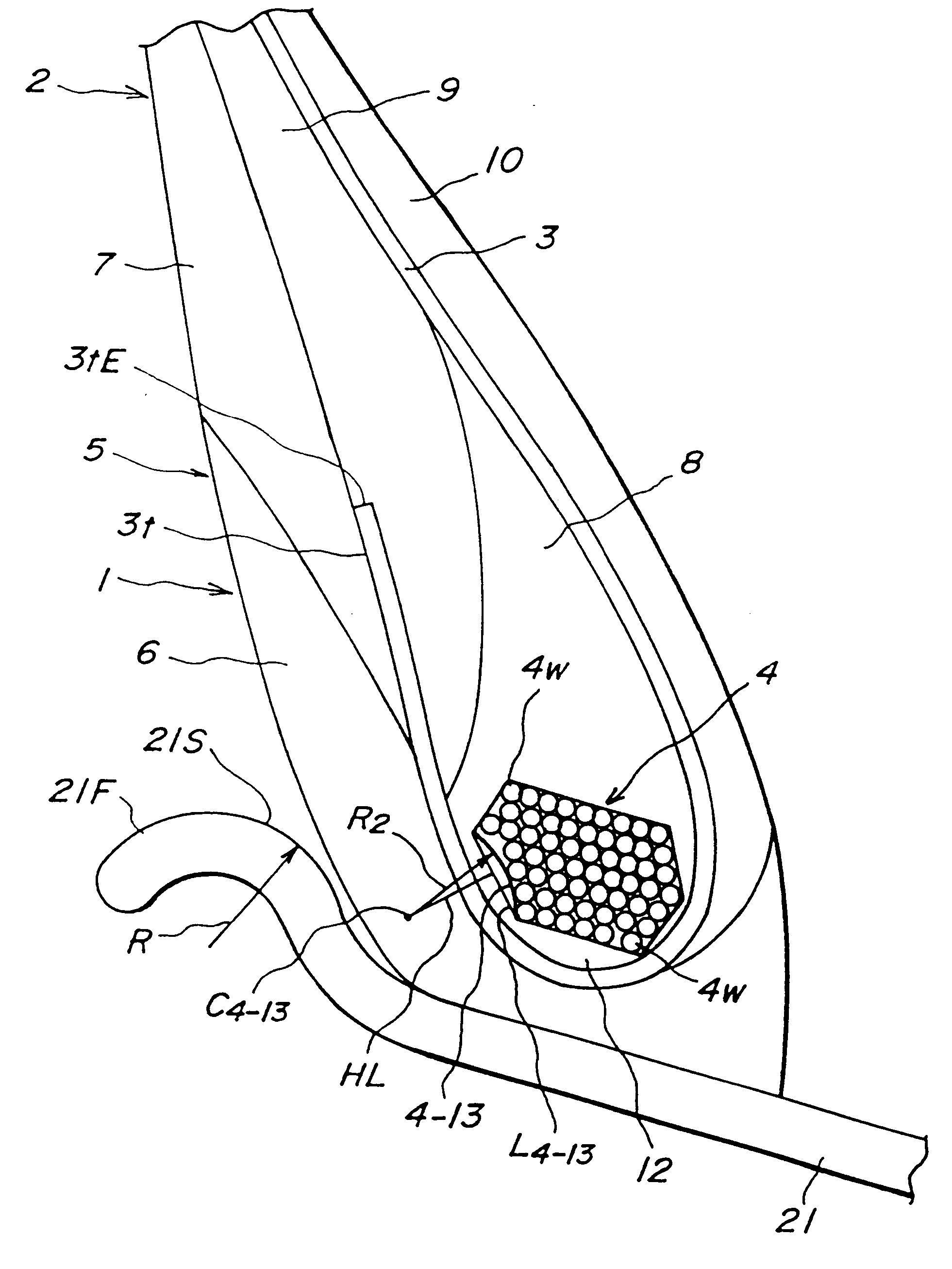
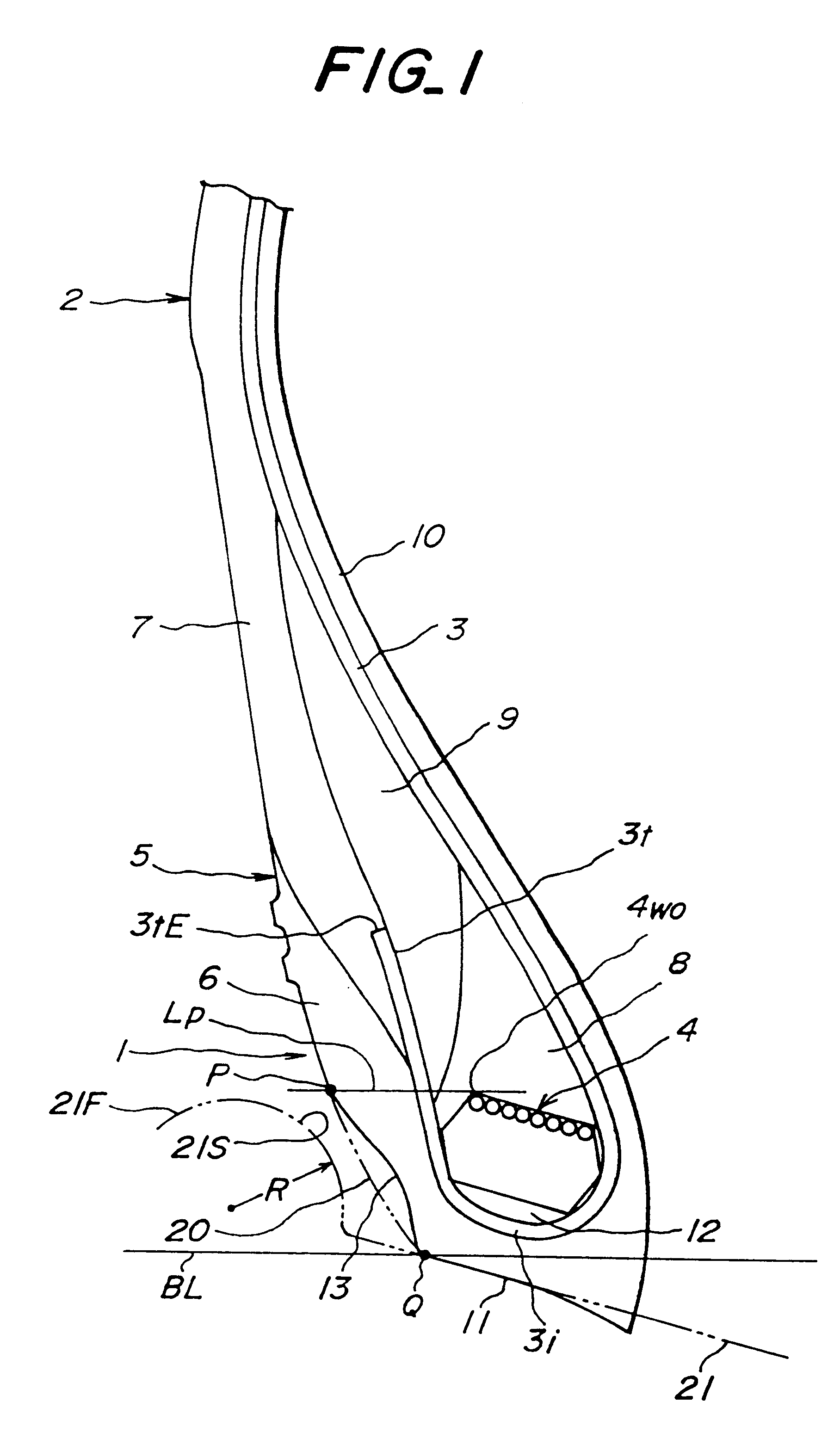
In this point, it can be said that the shifting, deformation and shape losing of the bead core considerably and badly affect the durability of the bead portion.
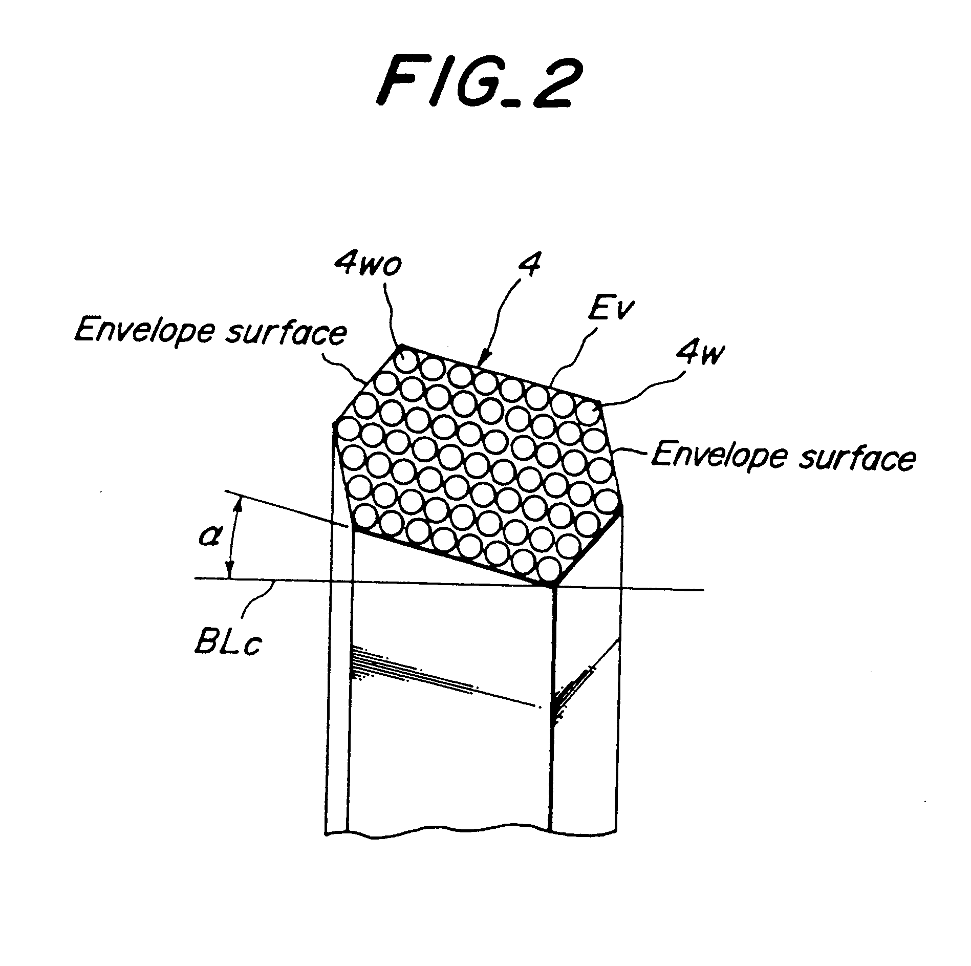
However, the shape of the bead core inside the tire is not necessarily maintained at an accurate polygonal shape, but is generally a shape somewhat shifting from a shape formed by connecting of line segments of n points to each other in turns.

