Needle and method for delivery of fluids

a technology of fluids and needles, applied in the direction of injection needles, intravenous devices, automatic syringes, etc., can solve the problems of unreliable needle types, inability to ensure accurate delivery rates, and inability to provide satisfactory solutions for needles. achieve the effect of reducing costs

Inactive Publication Date: 2002-02-12
ALKERMES PHARMA IRELAND LTD
View PDF17 Cites 233 Cited by
  • Summary
  • Abstract
  • Description
  • Claims
  • Application Information

AI Technical Summary

Benefits of technology

Suitably, the sharpened end is provided with a terminal orifice to assist in delivery of the liquid through the needle.
Preferably, the or each aperture is formed by the operation of a grinder on the surface of the shaft. Alternatively, the or each aperture is formed by another machining operation such as milling (although grinding is at present preferred due to lower costs and the fact that it is not as likely to give rise to difficulties such as chips being produced by the operation.

Problems solved by technology

This type of needle has been found to be unreliable in ensuring accurate delivery rates, in particular when used in conjunction with an infusion pump or some other delivery device which depends for delivery on the magnitude of pressure applied to the liquid being delivered.
The lack of accuracy is thought to be due to the build up of pressure at the delivery point which opposes the driving pressure applied to the liquid.
None of these needles provides a satisfactory solution to the problem of ensuring accurate delivery using a delivery device in which the delivery rate depends on the generation of pressure, because in each case, the problem which has been addressed has been the provision of an additional orifice which will not become plugged upon insertion or which will not rest against a vein wall.
While these problems must be addressed in designing a needle for use with an automated drug delivery device, it has been found that these factors alone do not account for the major variations in delivery rate which occur when using a device which depends for delivery on pressurising a supply of drug.
Without wishing to be bound by any theoretical explanation, it is conjectured that the major obstacle to ensuring accurate delivery rates is not that the orifice becomes plugged, but rather that the difficulty arises from poor absorption by the tissue adjacent to the orifice(s), and / or from variations in the structure of the tissue at the orifice.
Nevertheless, it is not practicable to replace conventional delivery needles with needles of the type disclosed by Huber or Copen because of the substantial difference in manufacturing cost involved.
In the case of small diameter needles such as needles having an external diameter of less than 0.7 mm and an internal diameter of less than 0.45 mm (approximately 22 gauge or higher), this is a relatively complicated task when compared to the preceding steps.
In all cases, the operations require careful positioning of the needle relative to the machining means, and a delicate machining of each and every needle.
The magnitude of the cost differential between such needles and conventional needles arises from the differences between the complexity of the manufacturing processes involved in each type of needle.

Method used


Image

  • Needle and method for delivery of fluids
  • Needle and method for delivery of fluids
  • Needle and method for delivery of fluids

Examples


second embodiment

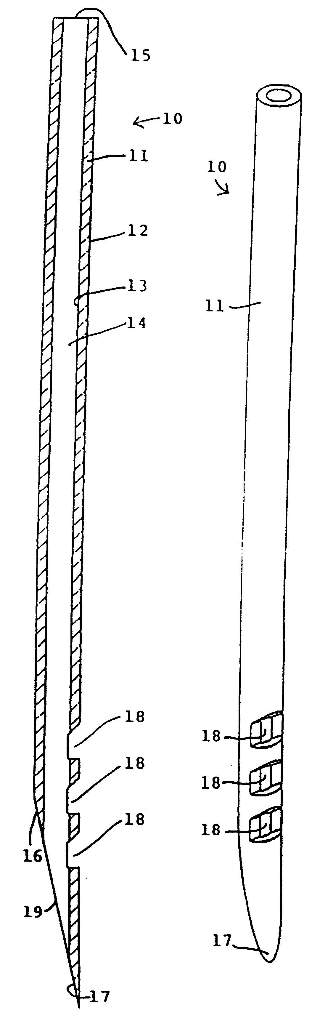
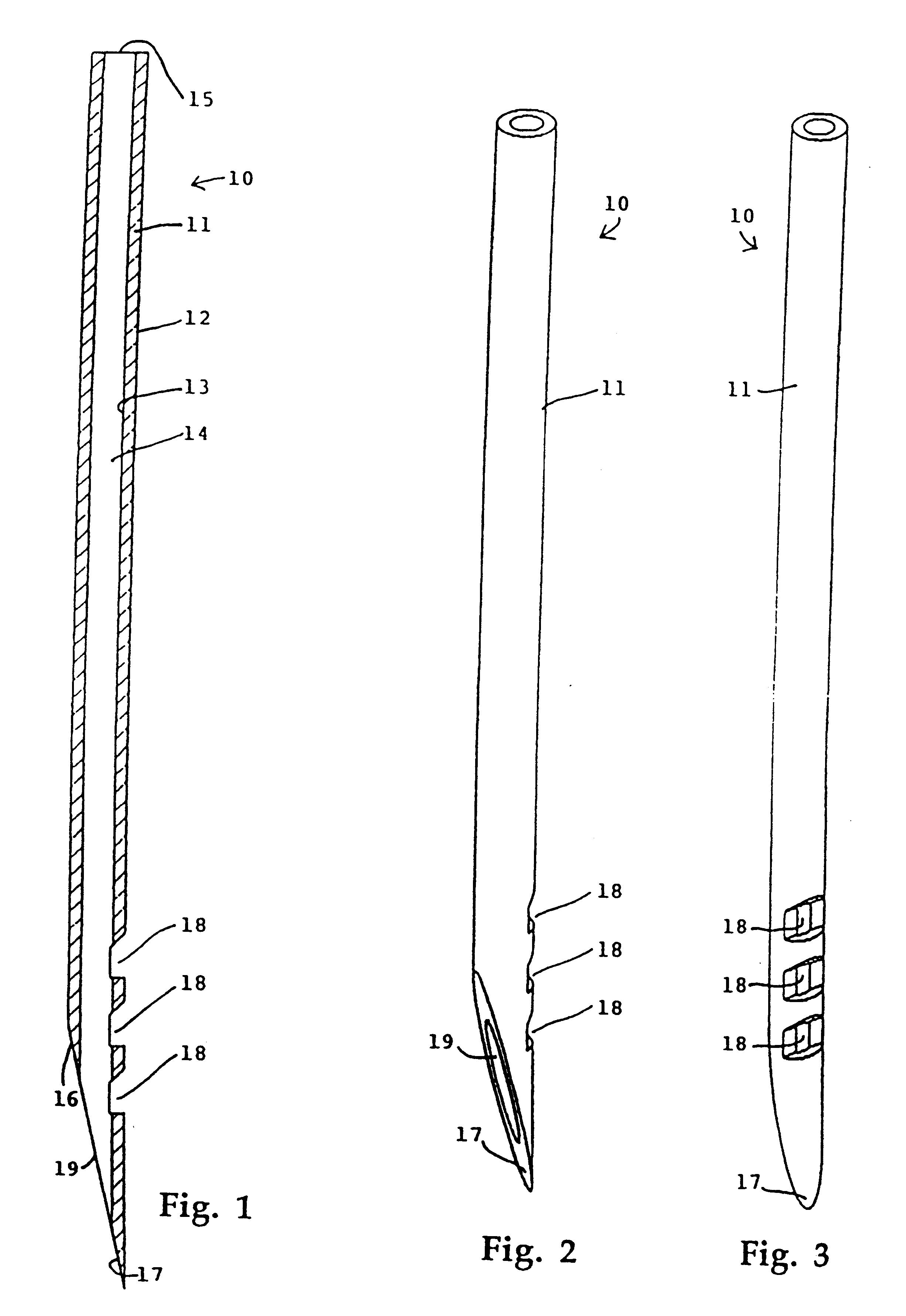
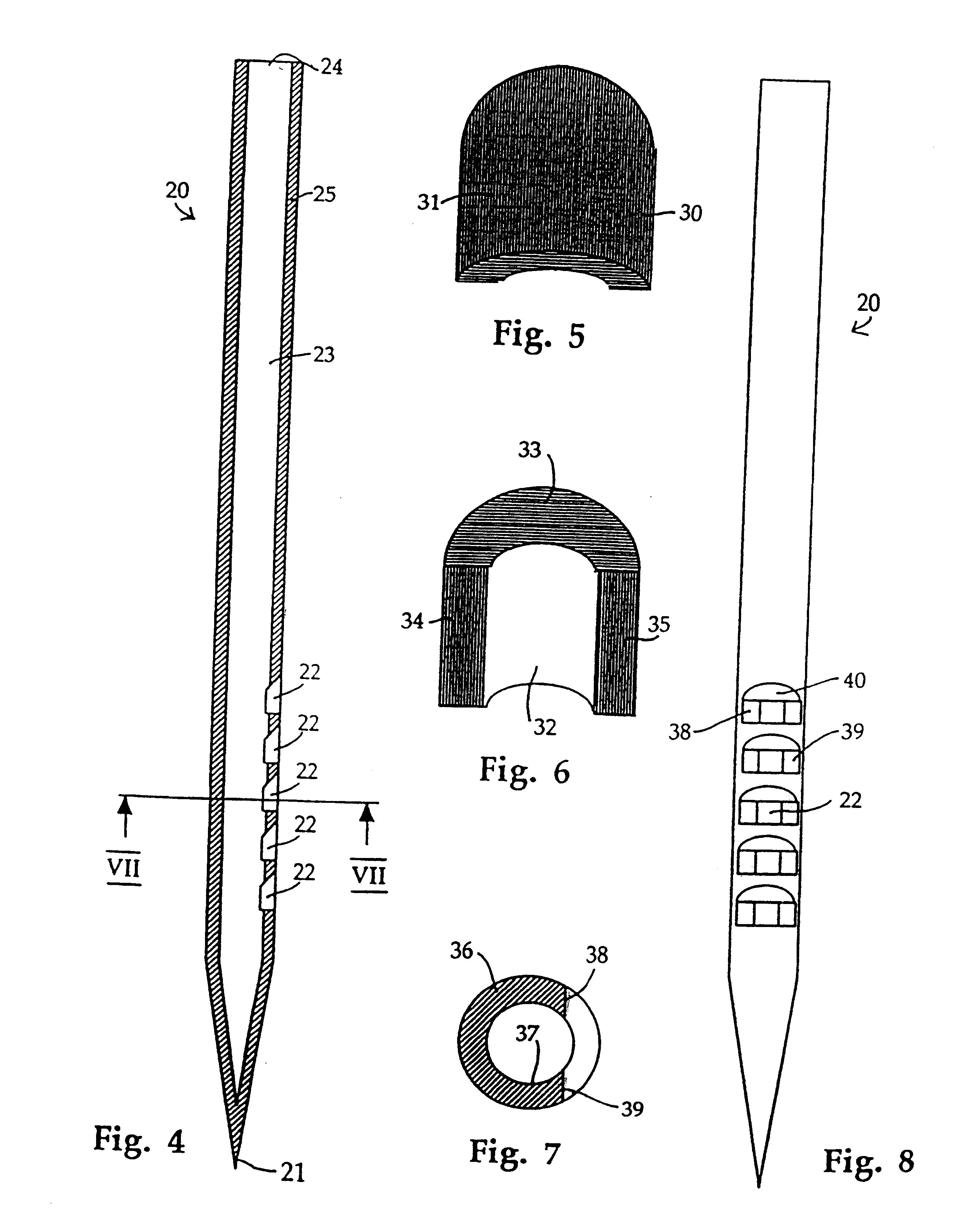
Similar apertures can also be seen in FIG. 4, in which needle according to the invention, indicated generally at 20, is shown. Needle 20 is identical to needle 10 (FIGS. 1-3) apart from the shape of the sharpened end 21 and from the fact that the side of the needle is provided with five rather than three apertures 22.

In needle 20, the sharpened end 21 is closed, i.e. the internal bore 23 is only open at the top 24 of the needle 20 and at the apertures 22. The number of apertures can be chosen to suit the delivery rate which is required and the site into which the shaft 25 is to be inserted. A needle inserted into an area of tissue which is rich in capillaries or into a vein will not require as many apertures as a needle inserted into a site which is deficient in blood vessels or a site at which the number of blood vessels varies over small distances.

FIG. 5 illustrates the shape of the apertures 18,22 in the needles 10,20 of FIGS. 1-3 and 4 by showing the shape of the material 30 whi...

third embodiment

In FIG. 11, there is indicated, generally at 60, needle according to the invention. In this embodiment, apertures 61 are formed by machining a row of cuts across the needle at an angle equal to the bevelled angle of the tip 62. Dotted lines 63 indicate the parallel paths of the cutter which creates the bevelled tip 62 and the apertures 61.

Referring additionally to FIG. 12, it can be seen that a plurality of needles 60 can be aligned adjacent to and parallel with one another but laterally displaced, and the ends 64 of the needles 60 can be bevelled by cutting the needles along this row (the path of the cutter again being indicated by dotted line 63. The apertures 61 (FIG. 11) can then be cut along a parallel path while the needles 60 are aligned as shown.

In FIG. 13, there is indicated, generally at 70, a liquid delivery device according to the invention, which is suitable for use as an automated drug delivery device. The device 70 comprises a housing 71 containing a reservoir 72 whic...


PUM


Abstract

A needle (10) for the delivery of a liquid to a subject comprises a shaft (11) having an internal surface defining a longitudinally extending internal bore open at one end (15) to receive a liquid supply, the other end (16) being sharpened for penetration of the skin of the subject. A plurality of apertures (18) are provided, each in the form of a cut extending across the external surface of the side of the shaft (11) at a sufficient depth to establish communication with the bore. The external aperture area is approximately three times greater than the internal aperture area, thereby ensuring that the liquid is delivered to a large surface area of tissue to improve absorption and eliminate fluctuations in the delivery rate. The needle (10) can be mass-produced by aligning a batch of shafts alongside one another and running a grinder across the surfaces of the shafts to create the apertures (18) in the entire batch of needles simultaneously.

Description

This invention relates to needles for the delivery of liquids to human or animal subjects.The standard needle used for subcutaneous or intramuscular injections is in the form of a hollow shaft provided with a sharpened open end. This type of needle has been found to be unreliable in ensuring accurate delivery rates, in particular when used in conjunction with an infusion pump or some other delivery device which depends for delivery on the magnitude of pressure applied to the liquid being delivered.The lack of accuracy is thought to be due to the build up of pressure at the delivery point which opposes the driving pressure applied to the liquid.Others have tried to combat the problem by designing needles which were intended to avoid the problem of pressure build up arising from the orifice becoming plugged by tissue on entry into the skin.U.S. Pat. Ser. No. 4,413,993 (Guttman), U.S. Pat. Ser. No. 4,790,830 (Hamacher), and U.S. Pat. Ser. No. 4,838,877 (Massau) each disclose a hypoderm...

Claims


Application Information

Patent Timeline
Patent Type & Authority Patents(United States)
IPC IPC(8): A61M5/20A61M5/32
CPCA61M5/3291A61M5/2053A61M5/2046A61M5/32
Inventor GROSS, JOSEPHDANON, HAIM
Owner ALKERMES PHARMA IRELAND LTD
Why Eureka
Try Eureka