Manufacturing method of suspension spring for car

a manufacturing method and suspension spring technology, applied in the field of suspension spring manufacturing, can solve the problems of insufficient raising of fatigue strength, difficult to provide compressive residual stress from the surface of the coil, and falling of fatigue strength

Inactive Publication Date: 2002-02-12
SHOWA CORP
View PDF4 Cites 35 Cited by
  • Summary
  • Abstract
  • Description
  • Claims
  • Application Information

AI Technical Summary

Problems solved by technology

In this coiled spring manufacturing method, to raise the residual compressive stress in the coil by shot peening, it is necessary to increase the particle diameter of the shot, to raise the surface hardness of the shot or to increase the shot speed; however, when this is done, the issue arises that because the surface roughness of the coil increases and consequently stress actually tends to concentrate rather than disperse, the fatigue strength falls.
However, with this coiled spring manufacturing method, although a two-stage shot peening is carried out, by this step alone it is difficult to provide a compressive residual stress from the surface of the coil to deep positions, and it is not possible to raise the fatigue strength sufficiently.
For example if a load less than 10% greater than the maximum in-use load of the coil is used, it is not possible to provide satisfactorily a compressive residual stress in a position deep from the coil surface.
Either case is undesirable, because the fatigue strength of the suspension spring decreases and it becomes impossible to satisfy predetermined endurance conditions.

Method used


Image

  • Manufacturing method of suspension spring for car
  • Manufacturing method of suspension spring for car
  • Manufacturing method of suspension spring for car

Examples


embodiment 4

Preferred Embodiment 4

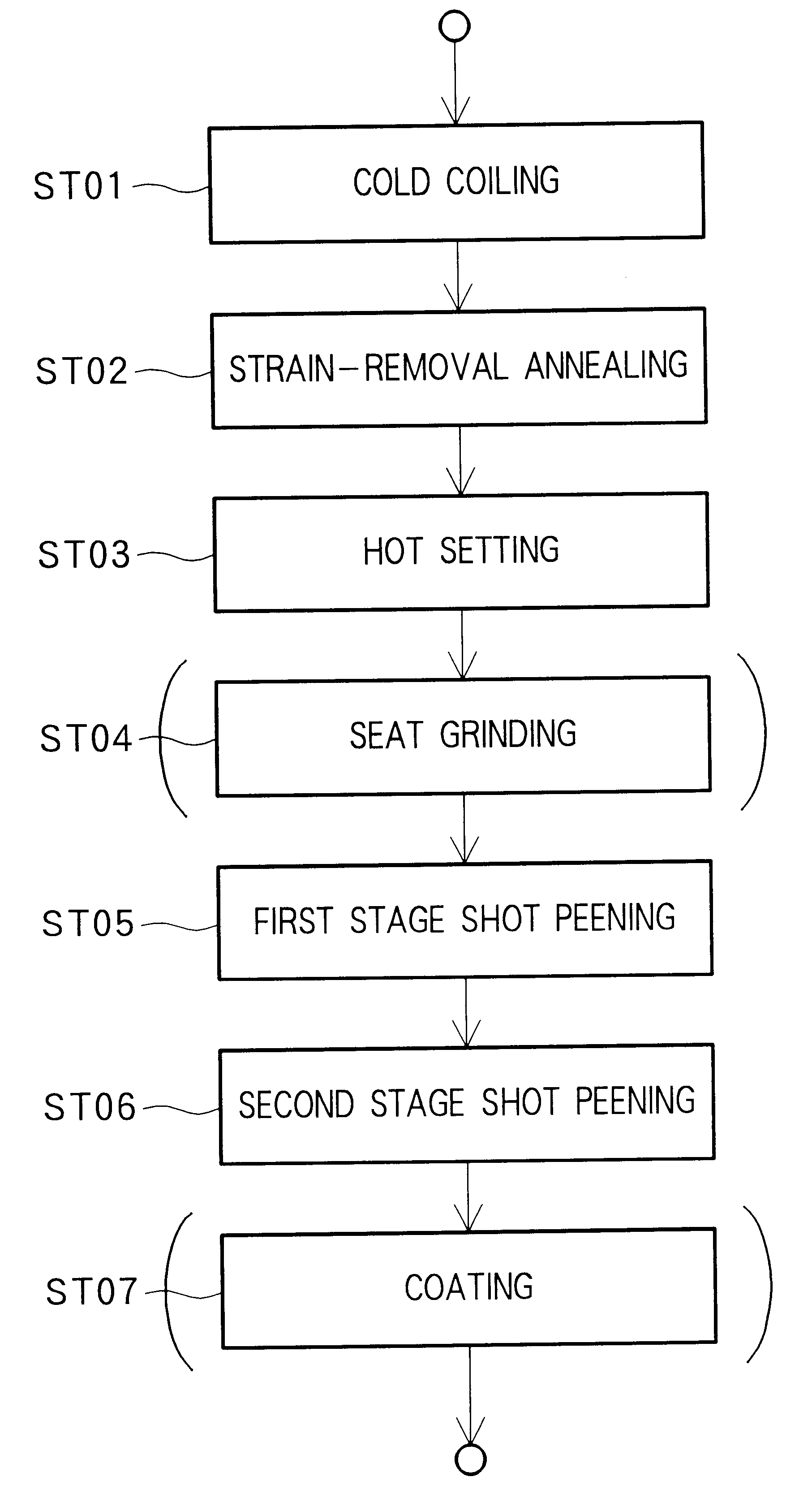
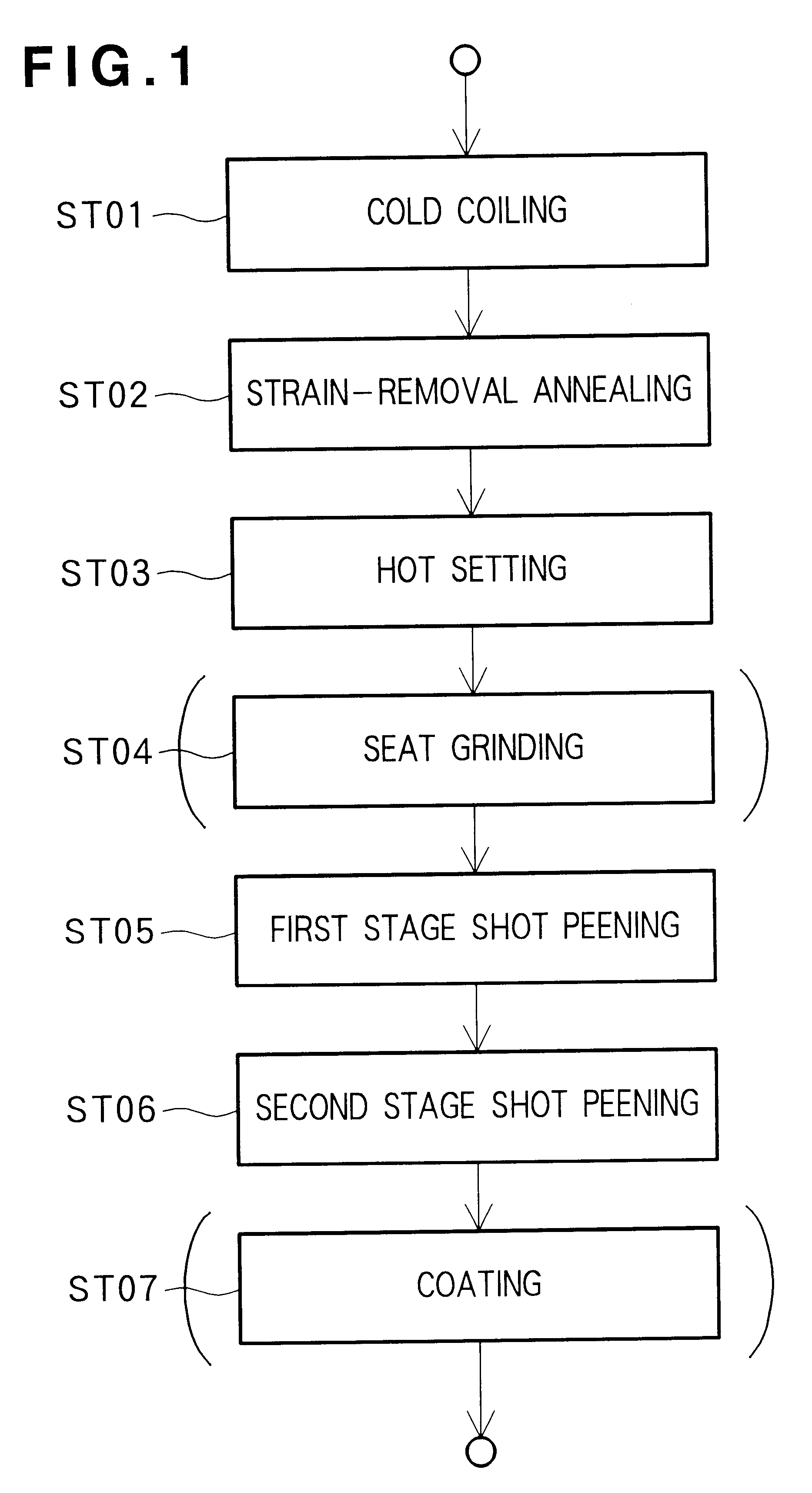
tensile strength 1910 N / mm.sup.2, hot setting, setting load 10% greater than maximum in-use load

The endurance test result was O.

embodiment 5

Preferred Embodiment 5

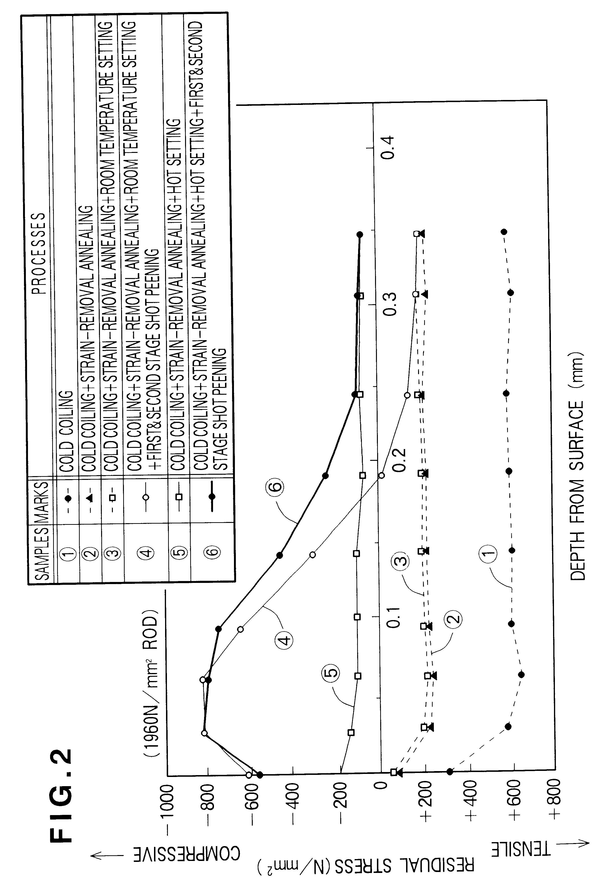
tensile strength 1960 N / mm.sup.2, hot setting, setting load 10% greater than maximum in-use load

The endurance test result was O.

embodiment 6

Preferred Embodiment 6

tensile strength 2020 N / mm.sup.2, hot setting, setting load 10% greater than maximum in-use load

The endurance test result was O.

In these fourth through sixth preferred embodiments the endurance test result is O for tensile strengths of 1910 to 2020 N / mm.sup.2, and because when suspension springs are manufactured to within this tensile strength range the hot setting can be carried out with the same conditions for all, manufacturability is also O.

Accordingly, the verdict on each of these fourth through sixth preferred embodiments is O (OK).


PUM

PropertyMeasurementUnit
tensile strengthaaaaaaaaaa
particle diameteraaaaaaaaaa

Abstract

A method for manufacturing a coiled spring having a high fatigue strength to be used for example as a suspension spring of a car using a rod of tensile strength 1910 to 2020 N / mm2 and diameter 8 to 17 mm. In a cold coiling step, the rod is formed into a coil. Annealing is then carried out to remove strains having arisen inside the coil during the coiling step. A hot setting step of utilizing surplus heat from the annealing step and applying a predetermined load to the coil to compress it for a predetermined time is then carried out. After that, multi-stage shot peening is carried out on the coil.

Description

1. Field of the InventionThis invention relates to a method for manufacturing a suspension spring used in an automotive vehicle and more particularly to a method for manufacturing a coiled spring having a high fatigue strength.2. Description of the Prior ArtIn coiled springs used as suspension springs in cars, for car body weight reduction, high fatigue strength is being required. In a known method for manufacturing a coiled spring having a high fatigue strength, a high tensile strength rod material made by drawing, quenching and tempering a spring steel rod is used; the rod material is subjected to the steps of coiling, heat-treating, grinding, and shot peening to impart residual stress thereto and then to the step of polishing to reduce surface roughness thereof.A method for manufacturing a coiled spring is disclosed, for example, in Japanese Patent Laid-Open Publication No. HEI-3-037434. The manufacturing steps of this coiled spring manufacturing method are shown in FIG. 4 hereof...

Claims


Application Information

Patent Timeline
Patent Type & Authority Patents(United States)
IPC IPC(8): C21D7/00C21D7/06C21D9/02C21D8/00B24C1/10B24C11/00F16F1/02
CPCC21D7/06C21D9/02Y10S148/908C21D8/00
Inventor TAKEZAWA, YOSHIYUKIICHIKI, KAZUOTADAKUMA, NAOKITANAE, TAKAHIROAKIYAMA, HIROSHI
Owner SHOWA CORP
Why Eureka
Try Eureka