Operating apparatus

Inactive Publication Date: 2002-03-12
MITSUBISHI ELECTRIC CORP
View PDF14 Cites 88 Cited by
  • Summary
  • Abstract
  • Description
  • Claims
  • Application Information

AI Technical Summary

Problems solved by technology

Thus the problem arises of light from the lamp 37 escaping from the notch 31d.
However in consideration of the rigidity of the spindle 31c, the effective minimum diameter is limited wh

Method used


Image

  • Operating apparatus
  • Operating apparatus
  • Operating apparatus

Examples


embodiment 1

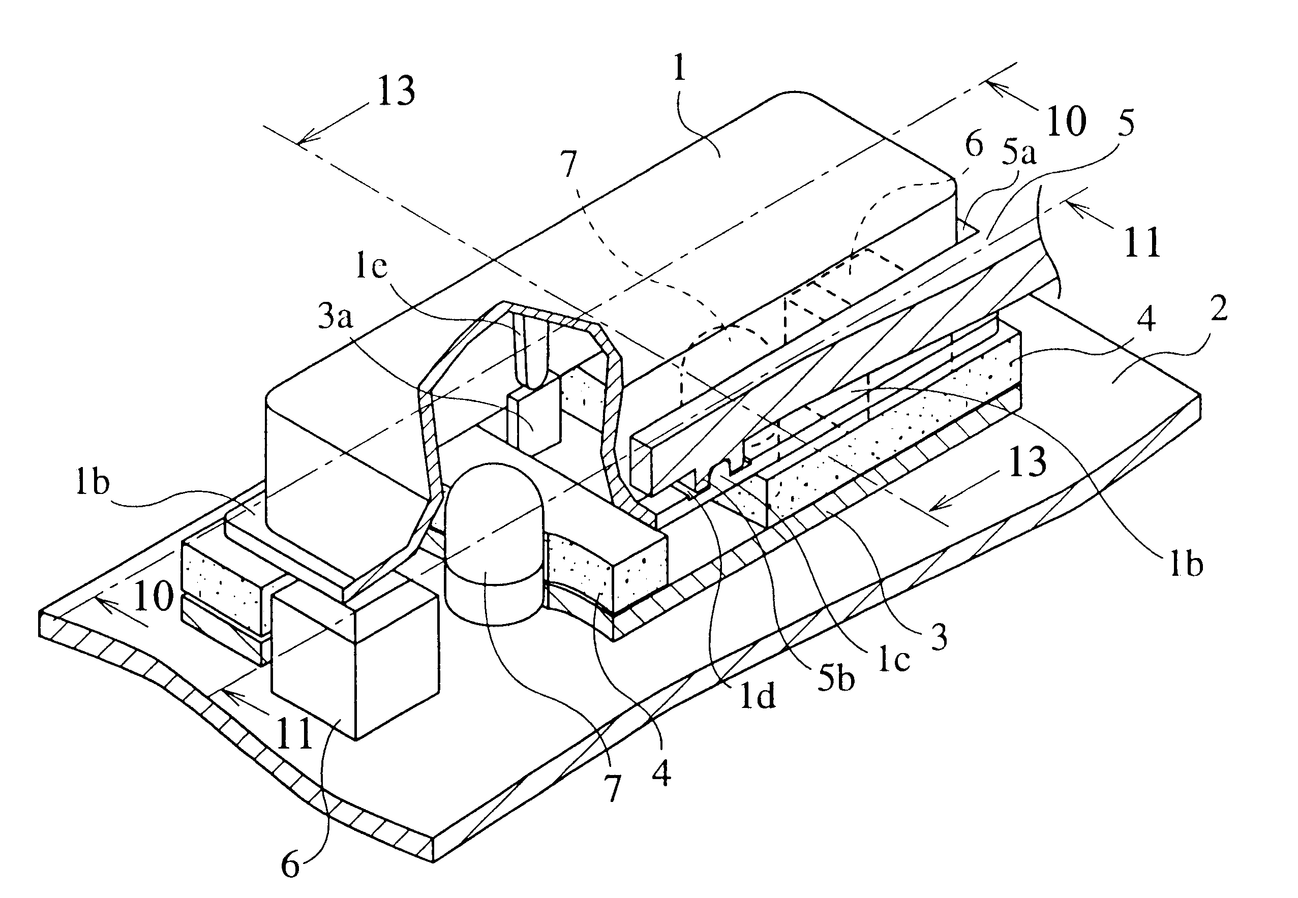
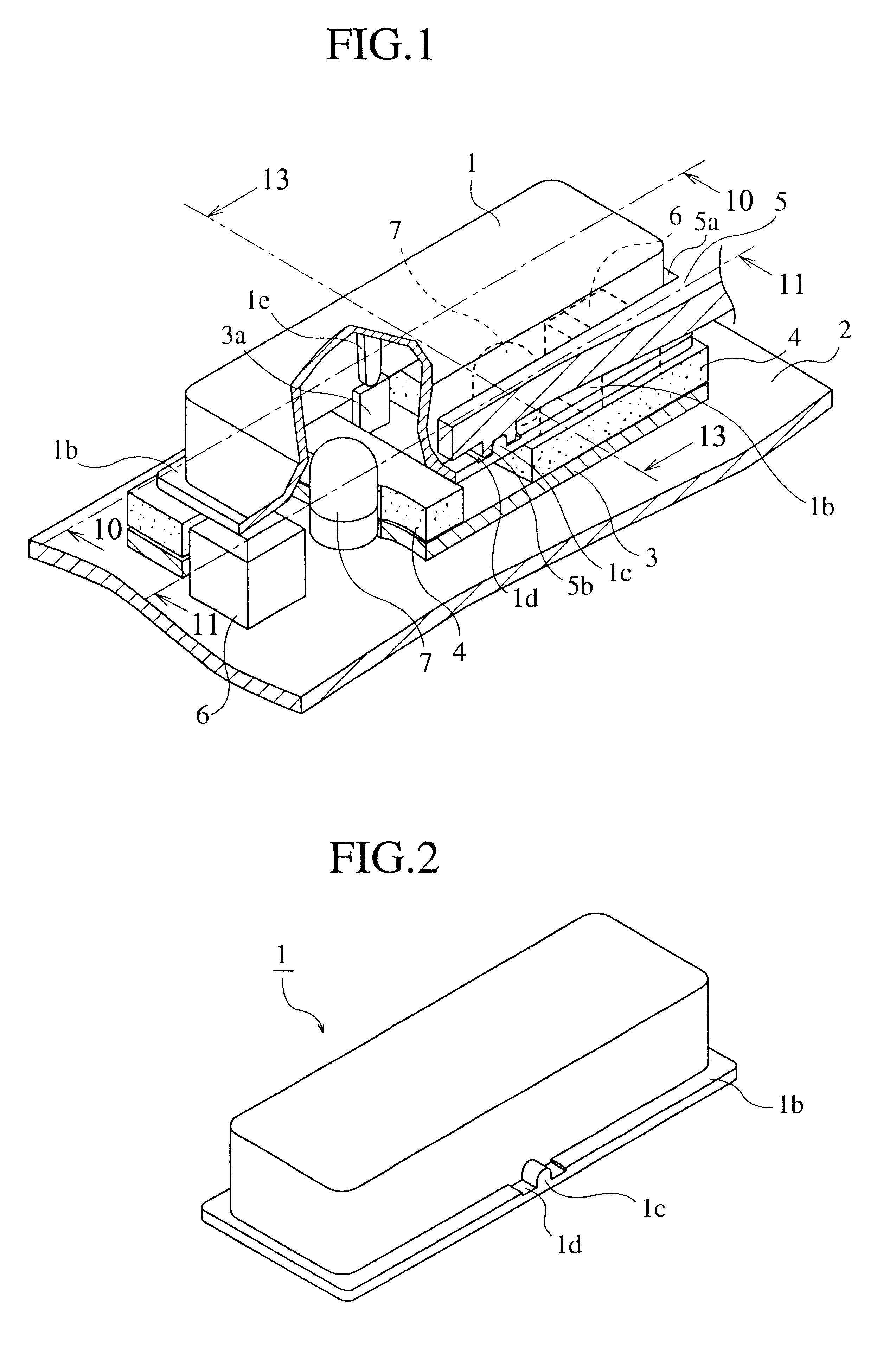
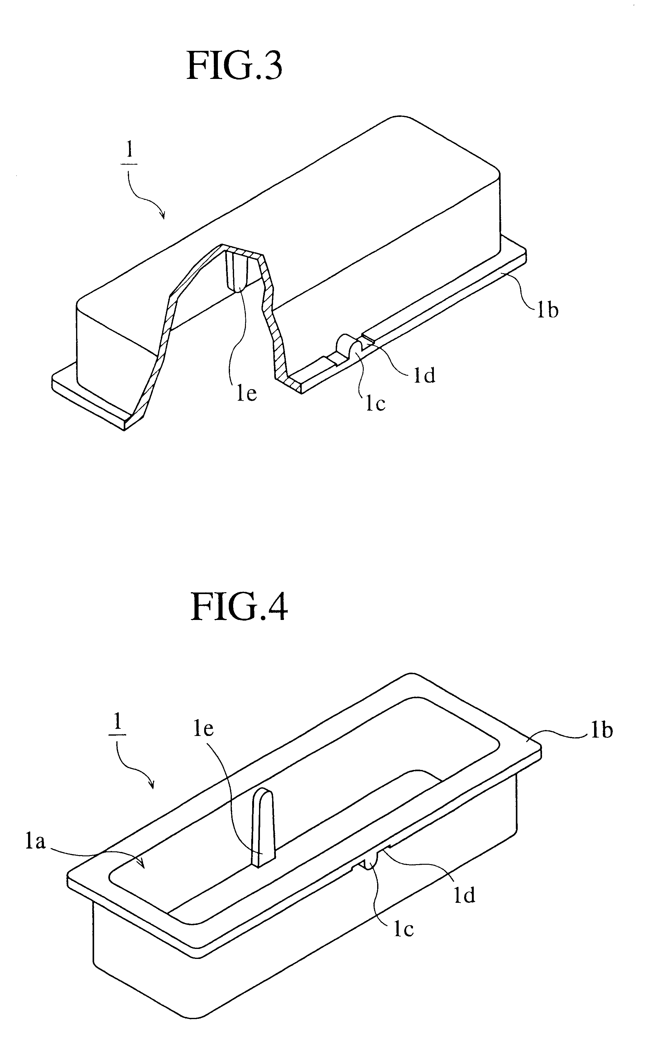
above was explained with a lamp 7 provided on a printed wiring board 2 and a flange 1b provided on a button 1. However the invention is not limited in this respect and when the device is not operated in darkness, such components need not be provided.

Embodiment 2

FIG. 15 is a schematic perspective figure of a second embodiment of the present invention. FIG. 16 is a cross sectional view along the line 16--16 of FIG. 15. FIG. 17 is a cross sectional view along the line 17--17 of FIG. 15. FIG. 18 is an enlarged view of the proximity of the outer support point of the button in FIG. 17. FIG. 19 is a cross sectional view along the line 18--18 of FIG. 15. FIG. 20 is a cross sectional view showing the operational state of a button.

In the figures, 10 is an elastic piece (button return member) which is integrated with one of the maintaining sections 3a of the button depression member 3 so as to abut with the lower face of the flange section 1b. The elastic piece returns to a pre-operational pos...

embodiment 2

the basis that an elastic piece 10 was provided on one of the maintaining sections 3a. However the invention is not limited in this respect and elastic pieces may be provided on both maintaining sections 3a and the same effect as described above will be obtained.

Furthermore as shown by FIG. 21, it is possible to freely change the operation of the button 1 by changing the elastic force through the use of an elastic piece 20 of a different thickness (for example two times the thickness of the elastic piece 10 in the figure). FIG. 21 is a cross sectional view showing an example of the invention as adapted to an elastic piece of modified width.

Furthermore the present invention was explained with a lamp 7 provided on the printed wiring board 2 and a flange 1b provided on the button 1. However the invention is not limited in this respect and such components need not be provided when the device will not be used in darkness.


PUM


Abstract

An operation device is provided with an outer support section 1c which projects towards an outer face of a button 1, an inner support section 1e which projects towards an inner face of said button 1, a maintaining section 5b which is provided on a decorative front panel 5 and which maintains said outer support section in free rotation, a maintaining section 3a which is provided on a button depression member 3 and which maintains said inner support section 1e in free rotation and a flange 1b which is provided continuously on the outer edge of the aperture of the button 1. Thus it is possible to provide a smaller device than the conventional example while maintaining the rigidity of the outer support section 1c. A smaller button 1 and smooth see-saw operation can be realized as well as reductions in escaped light.

Description

The present invention is related to an operation device which is used in an car audio system and which performs the switching of input operations by the so-called see-saw method.PRIOR ARTAn operation device which performs various kinds of switching operations is provided, for example, in a control panel of a car audio system. This type of device is provided with a depressable button (hereafter simply called "button") for performing the switching of input operations by the so-called see-saw method between two functions such as fast-forwarding or reversing a cassette tape. Furthermore the button of the operation device is formed so as to be illuminated from the rear so that the button is visible in darkness.A conventional device will be explained below with reference to the accompanying figures. FIG. 22 is a schematic perspective view of a conventional operation device. FIG. 23 is a plan view of a button. FIG. 24 is a lateral view of button. FIG. 25 rear view of a button. FIG. 26 is a...

Claims


Application Information

Patent Timeline
IPC IPC(8): H01H23/00H01H23/30H01H23/14H01H23/16H01H23/02
CPCH01H23/006H01H23/025H01H2221/016H01H23/16H01H23/30H01H23/143
Inventor IKUNAMI, TAKAHIRO
Owner MITSUBISHI ELECTRIC CORP
Why Eureka
Try Eureka